
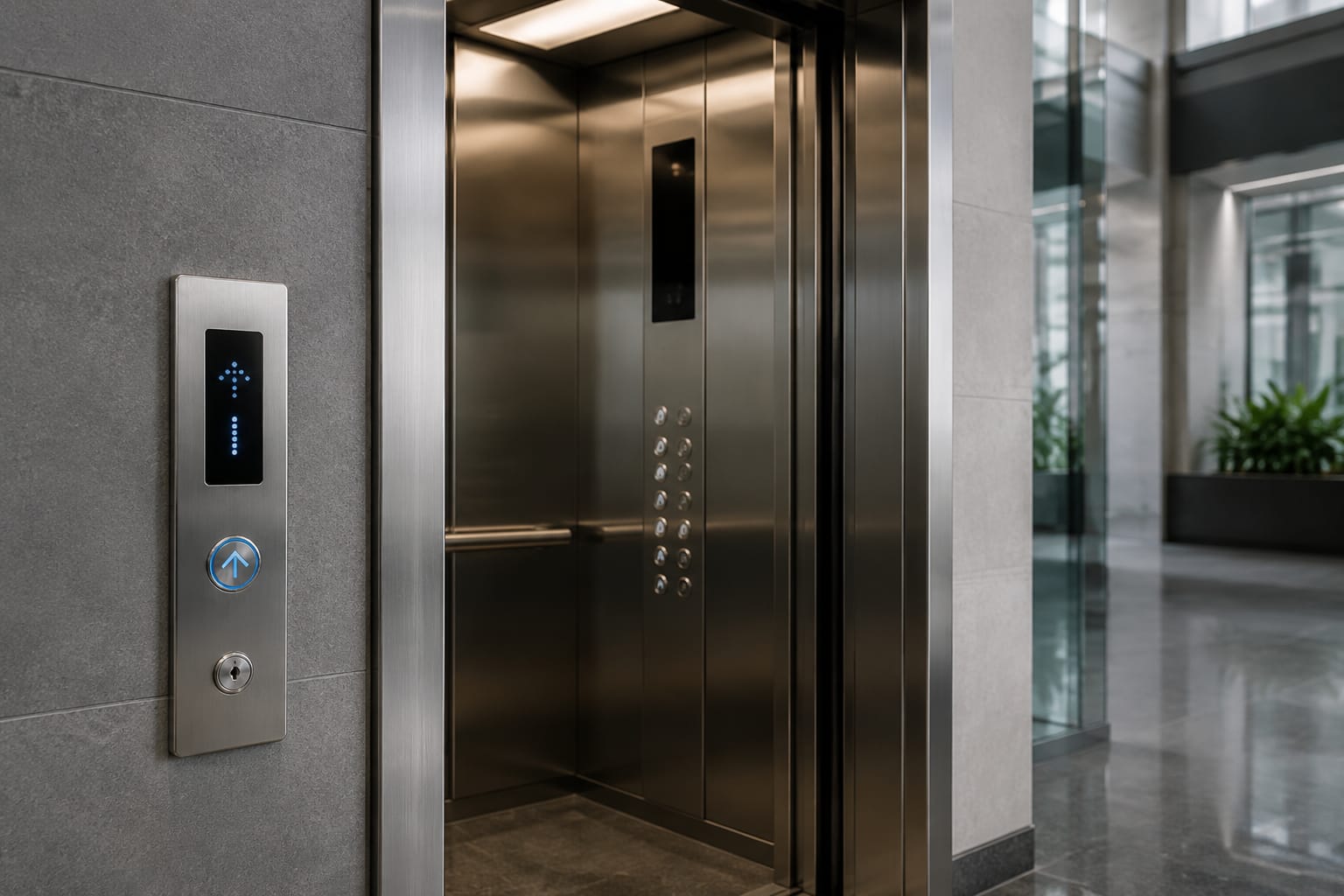
ThyssenKrupp elevator buttons should be sourced by the exact fixture and electronic interface, not by appearance alone. A round or square button that looks similar may have a different cutout, mounting method, voltage, illumination circuit, connector, or communication relationship with the car operating panel (COP) or hall call board.
For a practical replacement assessment, document where the button is installed, identify the panel and controller family, measure both the button and panel opening, and photograph every label and connector. That record helps distinguish a direct replacement from a part that requires a complete panel, board, harness, or modernization solution.
Car and landing button locations
Start by defining the button’s location and function. Elevator fixtures are often grouped by where they are installed, and a supplier needs that context before determining whether a replacement is appropriate.
Car operating panel buttons
The car operating panel is inside the elevator cab. It may include:
- Floor-selection buttons
- Door open and door close buttons
- Alarm and emergency call buttons
- Fire service controls, where applicable
- Key switches and restricted-access buttons
- Direction or information displays
- Braille, raised lettering, or tactile floor markings
Document whether the failed item is an individual pushbutton, a button assembly with a lens and retaining hardware, or part of an integrated COP module. On some panels, a visible button can be removed from the front; on others, service access is from behind the panel and may require disassembling connected components.
For a nonstandard cab interior, record whether the fixture is installed in a narrow jamb panel, sidewall panel, rear panel, or an oversized destination-control interface. Panel location can affect cable routing, available depth, and replacement options.
Hall stations and landing call buttons
Landing fixtures are installed outside the elevator at each floor. Their components may include:
- Up and down call buttons
- A single call button at terminal landings
- Hall lanterns and direction indicators
- Position indicators or arrival chimes
- Firefighter operation or emergency communication fixtures
- Destination-entry keypads or touch displays
A hall call button may be a standalone mechanical button, but it can also be part of a call station board that controls illumination, receives signals from the controller, and communicates with other landing devices. Do not assume a replacement hall button is independent just because it has a separate faceplate.
For electronic hall fixtures, compare the complete assembly with touch hall-call button board elevator parts only after documenting the original board identification and wiring.
Why location changes the replacement decision
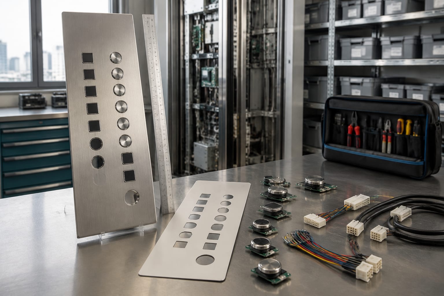
A car button generally interfaces with the cab wiring and COP circuitry, while a landing button may depend on a hall call board, serial bus, or terminal-specific configuration. The same symbol, lens color, or button shape does not establish interchangeability between these applications.
Also note whether the building has a single elevator, a duplex, or a larger group. Group operation can influence hall-fixture behavior, especially for directional indications, destination dispatch, and display functions.
Identify the panel and controller family
The term “ThyssenKrupp elevator buttons” covers equipment installed across multiple product generations and system designs. Some installations may also use TK Elevator branding following the business name change. Branding on the panel is useful, but it is not enough to identify the part.
Photograph and record information from the fixture, COP, controller, and, when safely accessible by qualified personnel, the rear of the assembly. Useful identifiers include:
| Record | Why it matters |
|---|---|
| Panel or station part number | May identify the complete fixture family and finish |
| Button or lens marking | Helps distinguish an individual component from a generic-looking equivalent |
| Controller model and serial information | Provides system context for electrical and communication compatibility |
| Board part number and revision | Often more important than the faceplate appearance for electronic fixtures |
| Installation or modernization documentation | Can reveal later fixture upgrades or mixed equipment |
| Building floor count and button legend scheme | Helps verify the required button set and labels |
Controller information is especially useful where the elevator has networked fixtures. A new button board may need to match a specific protocol, address scheme, firmware generation, or harness arrangement. A physical fit without a correct electrical interface can leave calls inoperative, illumination incorrect, or displays blank.
Do not infer a controller family from a cab logo, button color, or door operator branding. Elevators can be modernized in stages, and an older cab may contain newer control equipment or replacement fixture boards.
Check for mixed or modernized equipment
Many buildings retain original entrances and cab finishes while replacing controllers, COPs, or hall stations. In that situation, the installed button may be associated with the modernization package rather than the original elevator manufacturer.
Signs of a mixed system include:
- Different branding inside the cab and in the machine room
- Replacement labels or unbranded fixture boards
- Newer displays fitted into older panel cutouts
- Adapter harnesses, splices, or non-original mounting plates
- A COP layout that differs between cars in the same group
Treat these signs as a reason to document more carefully, not as proof that a generic component will work.
Measure button and cutout dimensions
Measurements should describe both the visible fixture and the space it occupies. A replacement can match the face diameter but still fail because its body, threads, clips, or connector require more clearance than the original panel provides.
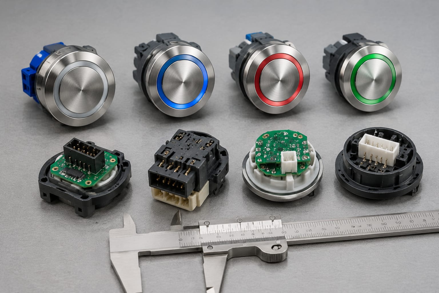
Use calipers where possible, then record dimensions in inches or millimeters consistently. Include clear photos with a ruler for additional verification, but do not rely on photographs alone for final dimensions.
Measure and record:
- Visible button face diameter, width, and height
- Panel cutout diameter or rectangular opening dimensions
- Panel thickness
- Total depth behind the panel
- Thread diameter and pitch for threaded pushbuttons
- Retaining nut, bezel, clip, or mounting bracket dimensions
- Spacing between adjacent buttons and displays
- Cable exit direction and clearance to nearby components
For round buttons, report the outside face diameter and the cutout diameter separately. For square or rectangular buttons, record width and height in both directions; a 1-inch-by-1.25-inch button is not interchangeable with a 1.25-inch square assembly.
Confirm the mounting approach
Common mounting approaches include threaded bodies with retaining nuts, snap-in clips, rear brackets, and components captured by a larger panel module. Check the back of the panel before ordering.
A front-mounted replacement may be impractical where a button is trapped beneath a decorative overlay, security plate, or display assembly. Likewise, an apparently standard button may use a proprietary rear carrier.
When an individual button cannot be matched reliably, a complete elevator car control panel, button, and display customization option may be more suitable for a cab refresh or modernization scope. That decision should be based on the panel layout, available mounting space, wiring condition, and required code updates, not solely on the failure of one button.
Check illumination and tactile features
Illumination and tactile details are functional requirements, not cosmetic extras. Verify how the original button responds during normal operation, after a call is registered, during inspection or fire service states, and when the elevator is out of service.
Record the following:
- Illumination color when idle and when registered
- Whether the button uses a lamp, LED, light ring, halo, backlit legend, or edge lighting
- Supply voltage and current information, if marked
- Number of terminals or conductors serving the light and switch contacts
- Whether illumination is controlled locally or by a board
- Lens color, symbol color, and engraving style
- Audible feedback, if present
- Raised characters, Braille, tactile arrows, or tactile symbols
A button with two terminals may be a simple contact, while one with additional terminals, a connector, or a board-mounted tail can have separate circuits for registration and lighting. Do not substitute a conventional dry-contact button for an electronically supervised or bus-connected device without confirming the circuit design.
Accessibility considerations in the United States
For public-facing elevators, button selection and placement may need to comply with applicable accessibility requirements, building codes, and the authority having jurisdiction (AHJ). Requirements can affect tactile markings, Braille, visual contrast, audible signals, control height, and operable force.
An individual replacement should preserve the required accessible features of the existing installation. A modernization project may trigger a broader review of fixture layout and compliance obligations. Confirm the project-specific requirements with the responsible code professional, consultant, or AHJ; do not assume an imported button face or a visually similar replacement meets the requirements for a particular property.
Record board codes and connectors
For electronic fixtures, board identification is often the deciding compatibility detail. A photo of the front face is useful for matching the appearance, but the rear board label, revision, connector arrangement, and harness information are usually what determine whether a replacement can communicate with the elevator system.
With power and safety procedures handled by qualified elevator personnel, photograph both sides of the relevant board. Capture labels clearly and avoid disconnecting connectors solely to obtain a photo.
Include these details in the record:
- Printed circuit board (PCB) part number
- Revision level, date code, and manufacturer label
- Barcode or serial number, where present
- Connector identifiers printed on the board
- Number of connector positions and number of populated pins
- Plug style, keying, latch location, and wire-entry orientation
- Wire colors and terminal labels
- DIP switch, jumper, or address-setting positions
- Damage such as corrosion, overheated areas, cracked solder joints, or loose connectors
A connector that has the same pin count can still be incompatible because of different keying, pin assignments, voltage, signal type, or addressing. Never match board assemblies by connector shape alone.
Preserve configuration information
If the existing board has DIP switches, jumpers, rotary addresses, or software labels, record the current state before removal. A replacement board may require the same configuration to operate correctly, subject to the manufacturer’s instructions and qualified installation procedures.
Do not copy settings blindly between cars. Two fixtures in one elevator group can use different addresses or functions even when their boards look identical.
Evaluate display and call-board integration
Displays and hall call boards add another compatibility layer. A floor indicator, directional lantern, touch interface, or call display may share power, communication, and mounting hardware with the button assembly.
First determine whether the failed component is truly separate:
- Does the display remain operational when the button fails?
- Is the button connected directly to the panel wiring or to a shared board?
- Does one board serve both buttons and indicators?
- Is the display a simple segmented indicator, LCD, dot-matrix unit, or touch interface?
- Are messages, floor labels, or directional arrows configured electronically?
- Does the fixture use a dedicated harness or a daisy-chain connection?
A board that controls call registration and display output should be evaluated as a complete electronic assembly. Replacing only the visible button may not resolve a fault caused by the board, harness, controller communication, or power supply.
For systems that use call-display assemblies, compare the board number, connector arrangement, display type, and installed function against 3600/5200 elevator call display boards and button parts. The product family name or visual layout is still not a substitute for confirming the exact installed part information.
Test the fault before specifying a part
A non-registering call can originate from the button contacts, LED circuit, board, connector, harness, input/output module, or controller logic. Qualified technicians should use approved troubleshooting procedures and site documentation to isolate the fault before a part is selected.
Useful observations include whether:
- The button mechanically sticks, cracks, or has no tactile response
- The button illuminates but does not register a call
- The call registers but illumination does not change
- Multiple buttons or floors have the same issue
- The display, lantern, or audible signal fails at the same time
- The fault appears only intermittently
These observations help prevent ordering a button when the underlying problem is elsewhere in the circuit.
Accessibility and durability checks
The right replacement supports reliable everyday use while retaining the features required for the installation. Evaluate the environment and service demands before choosing a component based solely on a part number or finish.
For durability, consider:
- Traffic level and expected frequency of use
- Indoor, parking-garage, exterior, or high-humidity exposure
- Vandal resistance requirements
- Cleaning products used by building staff
- Resistance to scratching, impact, and discoloration
- Availability of replacement lenses, legends, and button modules
- Finish compatibility with the surrounding panel
Button faces, tactile symbols, and illumination should remain legible under the site’s actual lighting conditions. For example, a polished metal panel can reduce visual contrast, while a dimly illuminated parking environment may make a subtle button halo difficult to see.
For accessibility, confirm the replacement maintains the existing control function and any tactile or visual indicators. A button that fits mechanically but removes raised markings, Braille, contrast, or audible feedback can create a usability and compliance issue.
When replacing one component in an older panel, inspect adjacent buttons as well. A single failed button may be isolated, but widespread lens cracking, inconsistent lighting, worn legends, or brittle wiring can make a planned panel or fixture update more practical than repeated individual repairs.
Prepare a complete sourcing request
A complete sourcing request gives a supplier enough information to assess potential compatibility without guessing. It also makes it easier for your team to compare alternatives, determine whether a direct replacement is realistic, and identify missing technical information before the elevator is taken out of service.
Include the following:
- Equipment context: Elevator manufacturer branding, controller information, building application, and whether the fixture is in the car or at a landing.
- Part identification: Every number on the button, panel, board, label, lens, and harness. Include board revision information.
- Clear photographs: Front and rear of the button or fixture, panel overview, cutout, labels, connectors, wiring, and any damage. Use even lighting and include a scale image where helpful.
- Measurements: Button face, cutout, panel thickness, rear depth, mounting hardware, and connector dimensions.
- Functional description: Button function, legend, illumination behavior, tactile features, display relationship, and observed fault symptoms.
- Quantity and consistency: Number required, whether all cars use the same part, and whether matching appearance across a bank of elevators matters.
- Project constraints: Repair versus modernization scope, intended installation date, required documentation, and any applicable accessibility or site requirements.
- Compatibility question: Ask whether the proposed item is a direct replacement, requires wiring or programming changes, or should be supplied as part of a larger assembly.
Avoid sending only a photo of the front face or a generic description such as “round ThyssenKrupp button.” Those details may start a search, but they cannot reliably establish fit, function, or interface compatibility.
Kelevator supplies multi-brand elevator spare parts for B2B importers, distributors, maintenance contractors, modernization companies, and OEM buyers. For an evaluation, provide the identification package above and ask for the proposed part’s dimensions, mounting method, electrical characteristics, connector details, and system compatibility to be confirmed before purchase or installation.
FAQ
Can I replace a ThyssenKrupp elevator button with a generic button?
Only after confirming the cutout, mounting, contact arrangement, illumination, voltage, connector, and controller or board interface. A generic button may fit a panel opening but fail electrically or omit required tactile and illumination features.
Is the controller model enough to identify the correct button?
No. The controller model provides useful context, but fixture packages can vary by installation, age, modernization history, and panel configuration. The button or board part number, measurements, rear photos, and connector details are also important.
Should I order a button or a complete board?
Order an individual button only when the fault is isolated and the replacement is confirmed to match. Consider the complete board or fixture assembly when the button is integrated with a display, touch interface, call station electronics, or shared illumination and communication circuitry.
What is the most important photo to provide?
Provide both front and rear photos. The front shows the legend, finish, and layout; the rear reveals mounting, terminals, connector types, labels, and board information that determine compatibility.
Related product references
For practical catalog examples related to this topic, review Elevator Car Control Panel Car Button Display COP Customization, Touch Hall Call touch button board elevator parts, and 3600 5200 elevator call display board button lift parts accessories. Confirm the exact model, dimensions, ratings, and connectors before ordering.