
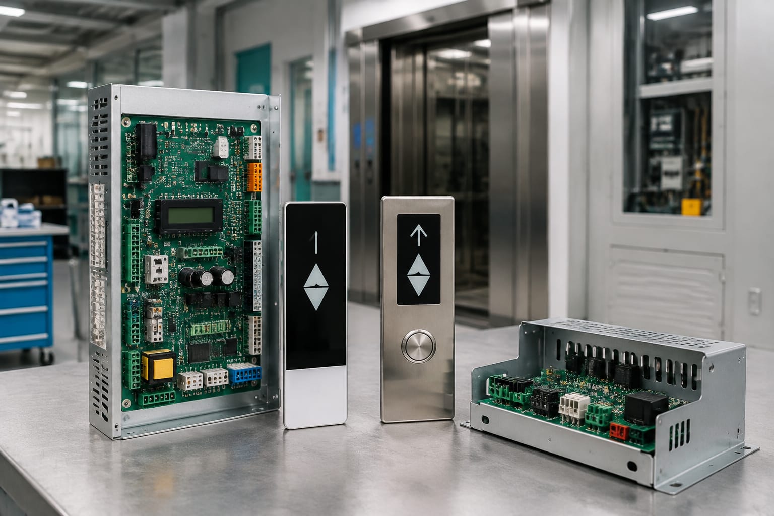
Ordering Schindler parts by a familiar description alone, such as “3300 controller board” or “door operator board,” is risky. The correct part must match the installed equipment family, its original part code, hardware revision, connector arrangement, electrical requirements, and system communication method.
Start with clear photographs of the removed component and its labels, plus the elevator model, controller or operator identification, and the jobsite’s existing wiring details. Those records provide a far stronger basis for a fit decision than a generic model reference.
Identify the Schindler equipment family
The equipment family is the first filter when sourcing Schindler elevator parts. A component may have a similar shape or a broadly similar function across installations while still being incompatible with the controller, door operator, car operating panel, or network in service.
Collect identification information from the equipment itself rather than relying only on building records. Modernization work, repair history, and previous component substitutions can make a site inventory incomplete or outdated.
Useful identification sources include:
- The controller cabinet data plate
- Labels on the existing circuit board or module
- Door operator nameplates and controller labels
- Car operating panel and display board markings
- Landing fixture labels, where present
- Equipment maintenance records and prior purchase orders
- Clear photos of board faces, connector sides, and mounting positions
Record the full wording on each label. A single suffix, revision identifier, or assembly code may distinguish a compatible replacement from a part intended for a related system.
For a board-level component, document both the board’s printed circuit board number and any separate assembly, serial, or production label. These references can serve different purposes. One may identify the bare board design, while another identifies a populated or programmed assembly.
Do not assume that the elevator’s controller family alone confirms every component. A car display, door operator controller, or interface board may depend on the fixture configuration, door equipment, software generation, or communication architecture used on that installation.
Common control and door components
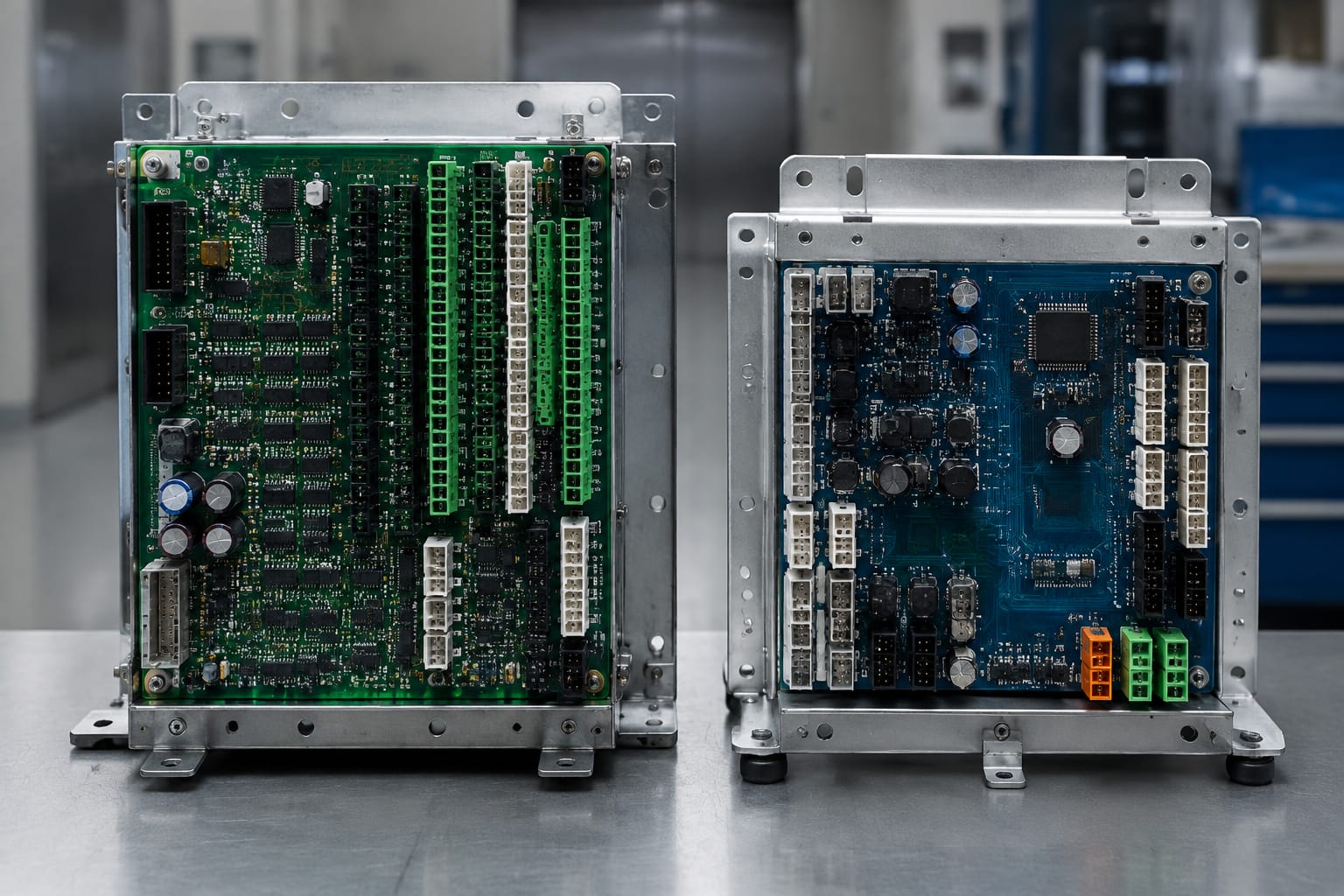
Schindler parts commonly sourced for maintenance, repair, or modernization work include control boards, car operating panel components, display assemblies, door operator controllers, power supplies, relays, sensors, switches, buttons, and harnesses. Each category requires a different compatibility check.
Controller and control-system boards
Control boards handle specific functions within the elevator system, such as processing inputs, managing outputs, monitoring safety circuits, or communicating with other equipment. Their appearance alone is not enough to establish interchangeability.
Before ordering a control board, compare:
- Original part and assembly codes
- Hardware revision and board version
- Number, type, and keyed orientation of connectors
- Terminal positions and labeling
- Mounting holes, brackets, and enclosure location
- Input and output voltage requirements
- Communication ports and bus connections
- Whether the part requires configuration, programming, or a compatible software environment
For applications identified as 3300 or 3600 equipment, use the component identification rather than treating either model name as a universal part number. A 3300/3600 elevator control board should be evaluated against the actual board label and installation details before it is treated as a replacement candidate.
Car operating panel and display components
Car operating panel, indicator, and display components often have visible cosmetic similarities but can differ behind the faceplate. Connector position, button matrix arrangement, display type, mounting dimensions, and communication protocol all affect fit.
When assessing a display board or COP-related assembly, verify:
- The panel or fixture family
- Display type and active area dimensions
- Board number and revision
- Connector type, pin count, and cable entry direction
- Mounting points and stand-off height
- Voltage supply and polarity
- Button, display, or network connection arrangement
- Whether the replacement includes only the board or the full display assembly
A 3300/3600 COP display board may be relevant when its identifying information matches the installed component. The exterior panel should not be used as the sole match criterion.
Door operator controllers and related parts
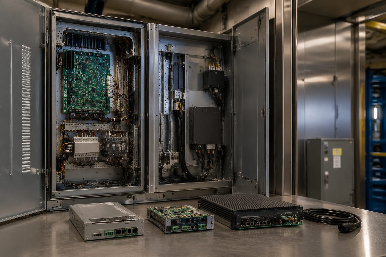
Door equipment is especially sensitive to model-specific differences. The operator controller must work with the installed motor, sensors, limits, harnesses, mechanical operator arrangement, and controller interface.
Check the existing door operator controller for:
- Operator family and controller label
- Motor voltage and motor connection details
- Encoder, sensor, limit, or position-feedback connections
- Door open and close signal interfaces
- Connector geometry and harness length
- Mounting dimensions and heat-sink clearance
- Parameterization or setup requirements after replacement
For an identified 3300 application, compare the installed label and connector details with the 3300 door operator controller listing. A part described for the same elevator family can still require confirmation at the operator-controller level.
Read board labels and part codes
The label on the installed part is usually the most useful source for determining what to order. Photograph it before disconnecting the component when possible. Good photographs preserve details that can be missed in a handwritten note, including barcode labels, revision marks, and smaller printed identifiers.
A typical circuit board can carry several codes:
| Marking type | What it may identify | Why it matters |
|---|---|---|
| OEM part number | The service or replacement item | Often the primary number to quote when sourcing |
| Assembly number | A specific completed board or module | May distinguish populated variants of the same board layout |
| PCB number | The bare board design | Useful for comparison, but not always sufficient to order |
| Revision code | Hardware generation or engineering change | Can affect connectors, components, or system compatibility |
| Serial number | Individual production tracking | Useful for records, but usually not the ordering number |
| Date or lot code | Manufacturing traceability | Can help identify production era, but does not prove fit |
| Barcode label | Machine-readable part identification | Photograph the entire label and its human-readable text |
Copy codes exactly, including dashes, spaces, leading zeros, and letter suffixes. Avoid shortening an unfamiliar code because a minor formatting difference can represent a different assembly.
Also distinguish printed silkscreen text from adhesive-label text. The silkscreen may identify the circuit board design; the adhesive label may identify the final part delivered for service. Both should be included in the sourcing package.
If a label is damaged or unreadable, use several corroborating details: front and rear photos, connector close-ups, mounting dimensions, nearby cabinet labels, and the equipment family. Treat visual comparison as supporting evidence, not a substitute for a readable part number when the electrical or system role is critical.
Compare 3300 and 3600 applications
“3300” and “3600” are useful starting references, but they should not be treated as proof that a component crosses between applications. The appropriate comparison is between the exact installed item and the candidate part, not between two broad elevator model names.
| Comparison point | Why it must be checked |
|---|---|
| Exact board or assembly code | Similar applications can use different assemblies |
| Revision level | Later or earlier revisions may change hardware or interfaces |
| Connector count and keying | A plug that looks similar may have a different pin arrangement |
| Physical mounting | Hole pattern, clearance, brackets, and orientation can differ |
| Supply voltage | Incorrect electrical requirements can prevent operation or damage equipment |
| Network or communication interface | Control-system communication must match the installation |
| Associated hardware | Door motor, display, harness, and fixture configuration can affect compatibility |
| Setup requirements | Some replacements may need configuration or commissioning procedures |
An item marketed as applicable to both families should still be matched by its part code, revision, connector layout, and functional role. Conversely, two components with the same basic board shape should not be considered interchangeable merely because they are installed in similar cabinet locations.
For contractors handling a repair under time pressure, the practical approach is to retain the removed part until the replacement is inspected and accepted. That gives the technician a direct reference for connector orientation, mounting hardware, jumpers, and labels.
Check revisions and connectors
Revisions deserve the same attention as the main part number. A revision can represent a minor manufacturing change, but it can also introduce a meaningful difference in hardware, firmware support, component placement, connector style, or interface behavior.
Compare revision information in this order:
- Match the complete OEM or assembly code.
- Match the stated revision whenever possible.
- If the revision differs, compare the supplier’s compatibility documentation against the installed part’s connectors, voltage, and function.
- Escalate uncertain substitutions for engineering or technical review before installation.
Connector layout is one of the fastest practical checks. Take straight-on, well-lit photos of every connector side. Include a ruler or other reliable dimensional reference where useful, but do not let a dimension replace a pinout or connector comparison.
Look for:
- Connector housing type and color, if relevant
- Pin count and row arrangement
- Keying tabs, notch position, and latch style
- Connector labels printed on the board
- Cable orientation and available clearance
- Terminal block locations and screw-terminal count
- Unused connector positions or jumper headers
- Heat-sink placement that may affect enclosure fit
Never force a connector that does not mate naturally. Mechanical similarity is not evidence of electrical compatibility, and an altered or forced connection can create a safety, reliability, or equipment-damage risk.
Confirm voltage and communication details
Voltage confirmation is essential for electrically active Schindler elevator parts. Verify the rating from the installed component label, wiring diagram, equipment documentation, or qualified technical records. Do not infer voltage from the elevator’s building supply or from another board in the same cabinet.
Confirm the following where applicable:
- Nominal input voltage and acceptable supply type
- AC versus DC supply
- Polarity for DC-powered components
- Output voltage requirements for connected equipment
- Fuse rating and protective-device arrangement
- Grounding or shielding requirements
- Motor rating for door operator-related components
- Communication bus, port, or interface details
- Termination, addressing, or configuration settings
Communication compatibility can be less visible than physical fit. A board can mount correctly and accept the same connectors while failing to communicate as expected if it is intended for a different system generation or configuration.
This is particularly important for displays, COP electronics, controller interfaces, and door-related modules. Where documentation does not establish compatibility, pause the order rather than assuming a common plug means common communication.
Electrical and control-system work should be performed by qualified elevator personnel following the applicable equipment documentation and site safety procedures. A replacement component does not remove the need for proper inspection, setup, and functional verification.
Evaluate supplier documentation
A supplier should be able to work from objective identification details. The useful question is not simply whether a supplier has “Schindler-compatible parts,” but whether the offered item can be compared clearly to the installed component.
Evaluate the product information and order documentation for:
- The part number or a clearly stated cross-reference
- Model or application scope, with relevant limitations
- Product photos that show the actual connector and mounting side when possible
- Revision information, if supplied
- A clear statement of whether the item is new, used, repaired, or another condition category
- Inclusions and exclusions, such as boards, covers, harnesses, or mounting hardware
- Technical information needed to verify voltage and connector fit
- Return, inspection, and commercial terms suitable for your procurement process
Be cautious with generic descriptions such as “fits Schindler elevator” when no part code, revision, or application detail is provided. That language may be useful for initial searching, but it is not enough for a high-confidence purchasing decision.
Kelevator supplies multi-brand elevator spare parts for B2B importers, distributors, maintenance contractors, modernization companies, and OEM buyers. For a sourcing inquiry, a concise identification package makes it easier to compare an offered component with the equipment in service: exact label photos, board photos, connector photos, model information, and the quantity needed.
Final sourcing checklist
Use this checklist before releasing a purchase order for Schindler parts:
- Record the elevator, controller, door operator, or fixture equipment family.
- Photograph the installed component’s front, rear, labels, and connectors.
- Copy the complete OEM part number, assembly number, and revision code.
- Verify whether the candidate is a board, module, complete assembly, or accessory.
- Compare mounting pattern, dimensions, orientation, and clearance.
- Compare connector type, pin count, keying, labels, and cable direction.
- Confirm input voltage, output requirements, polarity, and motor details where applicable.
- Confirm communication interface, addressing, or configuration requirements.
- Review any stated revision differences and documented limitations.
- Confirm what hardware, cables, software, or setup steps are included or required.
- Retain the removed part until the replacement has been inspected and accepted.
- Have qualified personnel complete installation, testing, and return-to-service procedures.
The strongest sourcing decision comes from an exact part-code match supported by a revision, connector, electrical, and application review. When any of those details differ, treat the item as a potential substitution that needs technical confirmation rather than an automatic replacement.