
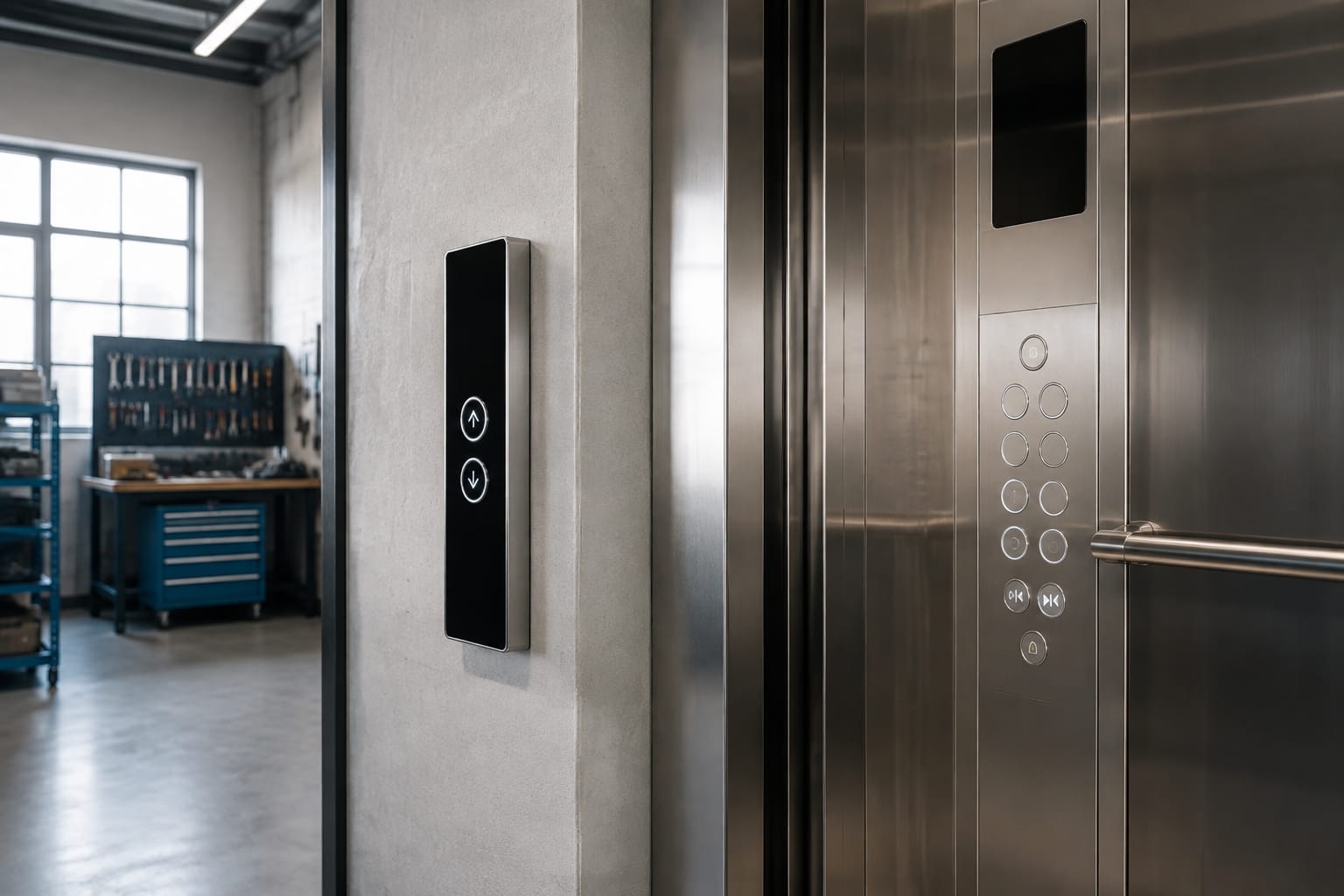
Replacing Schindler buttons correctly starts with identifying the complete assembly, not just matching its visible shape. Record whether the button is in the car operating panel (COP) or landing operating panel (LOP), then confirm the model family, button technology, cutout and bezel dimensions, illumination, symbol, board code, and connector arrangement before ordering.
A button that looks correct can still be incompatible with the existing panel electronics or mounting method. For maintenance contractors, modernization teams, and parts buyers, a disciplined identification process reduces return risk, avoids panel damage, and helps keep the elevator configuration consistent.
Schindler COP and LOP button functions
Schindler buttons serve different functions depending on where they are installed. The first selection decision is whether the part belongs in a COP inside the elevator car or an LOP at the landing.
A car operating panel (COP) contains controls used by passengers inside the car. Typical COP button functions include:
- Floor selection
- Door open and door close
- Alarm or emergency call functions
- Stop or inspection-related functions where applicable
- Special-access functions, such as key-operated or restricted-floor controls
A landing operating panel (LOP) contains hall call controls outside the elevator car. Typical LOP functions include:
- Up call
- Down call
- Single-direction call on a terminal floor
- Accessibility-related call functions in some installations
The same circular, square, or touch-style interface may be used in both panel types, but it should not be assumed to be interchangeable. A COP floor button and an LOP hall-call button may use different symbol overlays, LED behavior, wiring, board positions, or controller communication.
Before removing a failed Schindler button, document these basics:
- Panel type: COP or LOP.
- Exact function: floor number, door control, direction arrow, alarm, or another control.
- Panel position: record row and column or measure from a fixed panel edge.
- Existing button or board markings.
- Whether nearby buttons share a common board, harness, or light guide.
For multi-button boards, one failed control may require a board-level replacement rather than a separate mechanical pushbutton. Inspect the back of the panel before deciding which type of part is needed.
Identify 3300 and 3600 applications
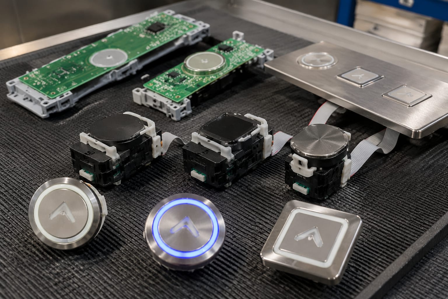
Schindler 3300 and 3600 applications require especially careful identification because replacement parts may be associated with different panel layouts, button technologies, and boards. Model-family information narrows the search, but it is not a complete compatibility check.
Start with the elevator documentation and the labels visible on the panel assembly. Useful sources include:
- Equipment identification records maintained by the building or service contractor
- The controller or car documentation, when accessible to qualified personnel
- Labels on the reverse side of the COP or LOP
- Printed markings on a button board, display board, or harness
- Clear photographs of the front and rear of the removed assembly
Do not identify an application from the elevator cab interior alone. A cab modernization, panel refresh, or prior repair may have changed visible fixtures while retaining or altering the underlying electronics. Likewise, a 3300 or 3600 designation does not establish that every panel in that installation uses the same board revision.
Record the application as a complete set
For sourcing purposes, combine the family name with physical and electrical evidence. A useful description might include:
- Schindler 3300 or 3600 application
- COP or LOP location
- Hall-call direction or car-button function
- Push-button or touch-button design
- Existing board code and revision, if marked
- Connector style, pin count, and keying
- Front-face dimensions and rear clearance
For touch-based hall-call assemblies, compare the original board against the product photos and documented identifiers, not the faceplate alone. Relevant examples include an ID touch button board for 3300 and 3600 elevator applications and a 3300 touch hall-call button display board. The buyer should still verify the exact board marking, connector, and physical layout for the installed panel.
Why model-family matching alone is insufficient
Ordering by “Schindler 3300 button” or “Schindler 3600 button” alone can lead to several problems:
- A board may fit the family but have the wrong connector orientation.
- The button may have a different illumination color or symbol arrangement.
- A hall-call assembly may be intended for the opposite direction or landing position.
- A newer or older board revision may not align with the installed hardware.
- A replacement may physically fit the opening but not communicate or illuminate correctly.
Treat the model family as one field in the identification record, not as the ordering specification.
Compare push and touch buttons
Schindler buttons may be conventional mechanical pushbuttons or touch-style assemblies. Their visible appearance, failure modes, mounting, and replacement process differ.
| Attribute | Mechanical push button | Touch button or board assembly |
|---|---|---|
| User action | Physical press with tactile movement | Touch or capacitive-style activation, depending on design |
| Typical replacement scope | Individual button, lamp/LED component, or button module | Board or touch assembly, sometimes with display elements |
| Key checks | Travel, bezel, mounting clips, terminals, lamp or LED | Board code, layout, connector, mounting points, display and touch area |
| Common visual issue | Cracked bezel, worn legend, sticking button | Unresponsive touch area, damaged surface, display or illumination fault |
| Installation concern | Incorrect seating can bind the button or damage clips | Electrostatic handling and connector alignment may be important |
| Compatibility risk | Same-size button may still have different terminals or lighting | Similar face layout may conceal different board revisions or wiring |
A mechanical pushbutton is not necessarily a simple commodity part. The rear terminal arrangement, switch action, illumination method, and mounting depth can all affect compatibility. A replacement that uses the wrong terminal configuration may not connect to the panel harness or may create a clearance issue behind the panel.
Touch assemblies require a broader check because the visible control can be integrated with printed circuitry, display functions, LEDs, and communication components. If a touch button is unresponsive, confirm whether the fault is isolated to the surface assembly, its connector, the board, or another panel component. Replacing a touch board without diagnosing a damaged harness or upstream issue can leave the original fault unresolved.
When handling any board-level component, use the procedures appropriate to the equipment and site. Avoid touching conductive contacts unnecessarily, protect the assembly from physical stress, and do not force a connector that does not align naturally.
Match dimensions and mounting
Dimensions determine whether a replacement will install cleanly, while mounting details determine whether it remains secure and operates correctly. Record both front-facing and rear-facing measurements.
At minimum, measure or photograph:
- Overall face or bezel width and height
- Diameter for round buttons
- Panel cutout dimensions
- Button projection from the panel face
- Rear depth available behind the panel
- Mounting-hole locations and spacing
- Clip, nut, screw, or bracket arrangement
- Orientation features such as tabs, flats, or keyed edges
Use a caliper when practical. Measurements taken with a tape measure can be useful for a preliminary inquiry but may not distinguish close variants. Photographs should include a scale reference and show the part from the front, side, and rear.
Check the panel opening, not only the old part
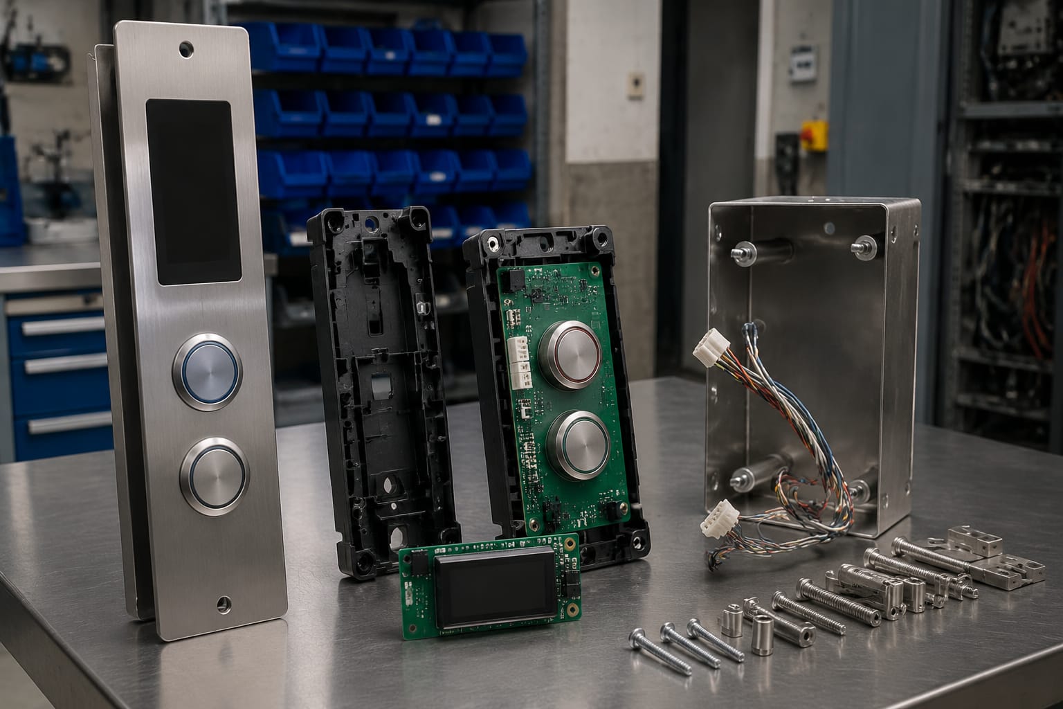
An old button may have been modified, damaged, or installed with an adapter. Confirm the actual panel cutout after removing the part. This is particularly important where a button is retained by clips or where the face bezel masks a larger opening.
For board-mounted or touch assemblies, record:
- Board length and width
- Mounting-hole count and positions
- Standoff height
- Location of connectors relative to the mounting holes
- Display-window position
- Orientation of the board in the panel
A board with the same overall dimensions but shifted mounting holes or a reversed connector can be unusable in the existing panel.
Preserve panel appearance and accessibility cues
When the replacement is visible to passengers, matching the original face geometry matters beyond fit. A different bezel height, legend size, or button profile can make a repaired panel look inconsistent and may affect the intended tactile experience.
For floor selection and direction buttons, compare the replacement with adjacent controls before installation. It should preserve the expected orientation, label position, and tactile markings where those are part of the original assembly. Do not substitute a visually similar button with a different function symbol merely because it fits the opening.
Check illumination and symbols
Illumination and symbols are functional requirements, not cosmetic details. Confirm how the original Schindler button indicates a registered call or selected floor, then match the replacement accordingly.
Document the following:
- Illumination color when active and inactive
- Whether the button is continuously illuminated or lights only after activation
- LED, lamp, light guide, or integrated display arrangement
- Symbol or floor marking
- Text, numeral, arrow direction, Braille, and tactile features
- Lens color and surface finish
- Whether the face is translucent, opaque, or backlit
A replacement can be mechanically and electrically connected yet still be wrong if it displays the opposite arrow direction, an incorrect floor legend, or a different active-state color. On an LOP, an up button and a down button may share the same housing but have distinct graphics and board positions. On a COP, a floor button must match both the intended floor designation and the panel’s illumination convention.
Avoid assumptions based on photographs
Product photos are helpful for comparing format and layout, but lighting can alter the apparent color of a lens or LED. Confirm the original part’s markings and active-state behavior directly where possible.
Also verify whether a displayed numeral or icon belongs to the button itself or to a separate board or display window. In a touch panel, the visible symbol may be printed on a cover layer while the electronics are part of a larger assembly. Ordering only the front component may not correct a board-level failure.
Verify board codes and connectors
Board codes and connector details are among the strongest compatibility indicators for electronic Schindler button assemblies. Record every visible marking exactly, including letters, numbers, dashes, spaces, revision identifiers, and date or lot labels where relevant.
When a code is partially obscured, photograph it rather than relying on memory. Similar characters can be easily confused, especially 0 and O, 1 and I, or 5 and S.
For each board or electronic button assembly, document:
- Full printed board code
- Revision level
- Manufacturer or internal label, if present
- Connector count
- Pin count for each connector
- Connector color, shape, and keying
- Cable exit direction and connector orientation
- Any jumpers, switches, or programmed labels present on the original
- Whether the original is a standalone module or part of a shared board
A relevant option for hall-call applications is this 3600 and 3300 elevator hall-call button board. Its applicability should be confirmed against the removed board’s markings and physical interface rather than assumed from the model-family wording.
Do not alter connectors to make a part fit
Splicing, repinning, trimming, or forcing a connector to adapt an uncertain replacement introduces avoidable risk. It can damage the panel, obscure later troubleshooting, or create an unreliable repair. If the connector does not match the original assembly, stop and reconcile the part identification before installation.
Similarly, do not assume connector compatibility solely from pin count. Two connectors with the same number of positions may have different keying, terminal spacing, pin assignments, or latch locations.
Test the panel after replacement
Testing should confirm both the replaced control and the surrounding panel functions. The exact procedure depends on the elevator system, site rules, and the qualifications of the personnel performing the work, but the verification should go beyond a single press.
After installation, inspect the panel before restoring normal operation:
- Confirm the assembly is seated evenly and securely.
- Verify that the face is correctly oriented and no gaps, sharp edges, or loose components remain.
- Check that no wires are pinched and all connectors are fully engaged.
- Confirm neighboring buttons, displays, and indicators have not been disturbed.
- Restore the panel according to the applicable service procedure.
Then test the intended function under controlled conditions:
- Press the replaced COP button and confirm it registers, illuminates, and clears or changes state as expected.
- For a hall-call button, confirm the direction symbol is correct and the call registers appropriately.
- Check that the illumination is visible and consistent with adjacent buttons.
- Test adjacent controls that share the same board or harness.
- Observe the panel for intermittent behavior, flickering, unexpected activation, or display faults.
A successful press test does not always prove long-term compatibility. If the replacement affects multiple functions, behaves inconsistently, or produces a new panel fault, recheck the board code, connector seating, and installation orientation before replacing additional parts.
Button sourcing checklist
A complete sourcing record makes it easier to compare options and reduces back-and-forth during procurement. Include the following with an inquiry or internal purchase request.
- Elevator model family, such as 3300 or 3600, when confirmed
- COP or LOP designation
- Button function and exact legend or direction
- Building equipment identifier or internal asset reference, where available
- Clear front, rear, and side photographs
- Full board code and revision markings
- Connector photographs showing pin count and keying
- Overall dimensions, cutout dimensions, and mounting-hole spacing
- Button technology: mechanical push or touch assembly
- Illumination behavior, lens color, and symbol details
- Quantity required and whether matched appearance across multiple buttons is needed
- Description of the failure: stuck, cracked, unlit, unresponsive, intermittent, or damaged board
- Whether the part is an individual control, a shared board, or a display/button assembly
For B2B buyers consolidating parts across several properties or service contracts, keep these records attached to the item in the purchasing system. A photo-and-code record is more useful for repeat orders than a broad description such as “Schindler call button.”
Kelevator supplies multi-brand elevator spare parts to B2B importers, distributors, maintenance contractors, modernization companies, and OEM buyers. When evaluating a replacement, provide the complete checklist information so the proposed part can be compared against the installed assembly on physical, functional, and electrical details.