
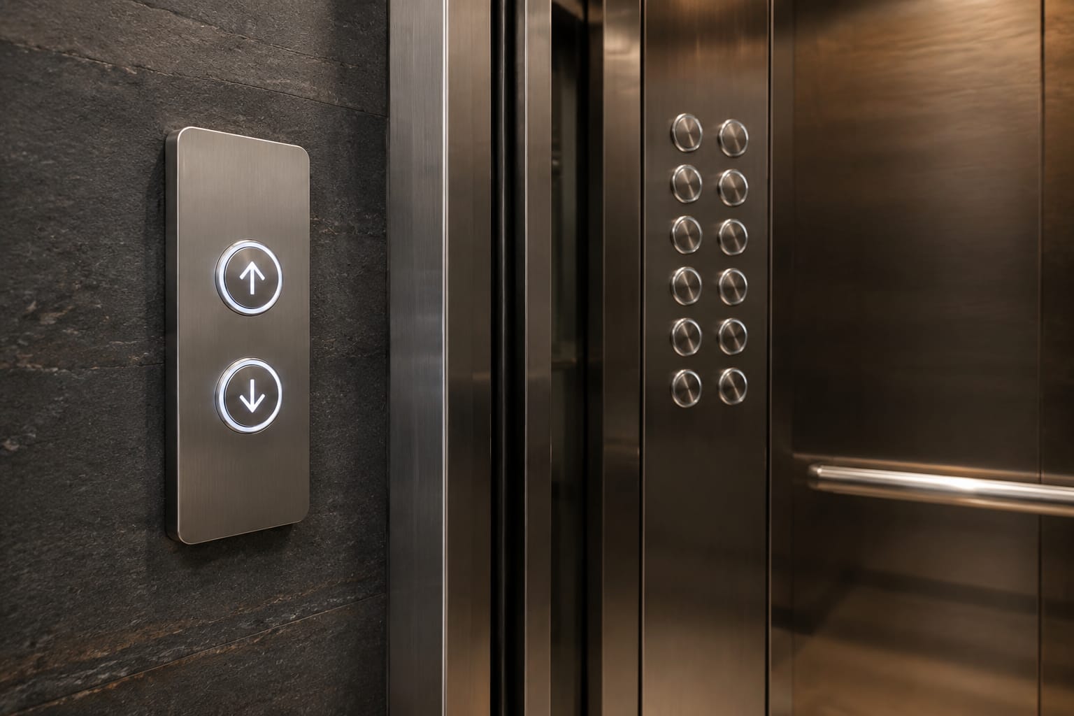
Replacing KONE elevator buttons is not a matter of matching the button face alone. A compatible replacement must match its location in the system, physical fit, illumination requirements, connector arrangement, and, where applicable, the associated car operating panel or landing call-board code.
Start by identifying whether the failed component is in the car or at a landing, then document the original part before removal. Photos of both sides, accurate measurements, the elevator model information, and readable board labels reduce the risk of ordering a button that looks correct but cannot be installed or communicate with the controller.
KONE Car Buttons Versus Landing Buttons
Car buttons and landing buttons serve different functions and are often built for different panel assemblies. Treating them as interchangeable is a common ordering error.
A car operating panel, commonly called a COP, contains buttons used inside the elevator car. These may include:
- Floor-selection buttons
- Door open and door close buttons
- Alarm or emergency call buttons
- Fan, light, key-switch, or service functions
- Car position and direction display components
Landing fixtures are installed outside the elevator at each floor. Their most common components are:
- Up and down call buttons
- A single call button for a terminal floor
- Hall lanterns and direction indicators
- Floor displays
- Destination-control interfaces, where used
The component location changes the compatibility questions. A car button may connect to a COP button board, while a landing call button may be part of a hall call station or connect to a dedicated call/display board. The face symbol, lens color, and button shape can be similar across locations, but the rear mounting, electronics, and communication interface may differ.
For car-panel repair work, compare the original assembly with the relevant KONE COB car button board parts. For landing stations that combine a display and call function, assess the complete board or display assembly rather than assuming the pushbutton is the only failed part.
| Feature | Car Operating Panel Button | Landing Call Button |
|---|---|---|
| Installation location | Inside the elevator car | Outside the elevator at a floor |
| Typical command | Select floor or car function | Request up or down travel |
| Related electronics | COP button board or car panel wiring | Hall call board, display board, or landing wiring |
| Common visual marking | Floor number, door icon, alarm icon | Up arrow, down arrow, or call symbol |
| Key compatibility concern | Panel cutout, button board connection, car function | Station configuration, direction function, board communication |
Before ordering, confirm the failed part’s actual panel location. “KONE elevator button” alone is usually not enough to identify a replacement.
Identify the Panel and Elevator Model
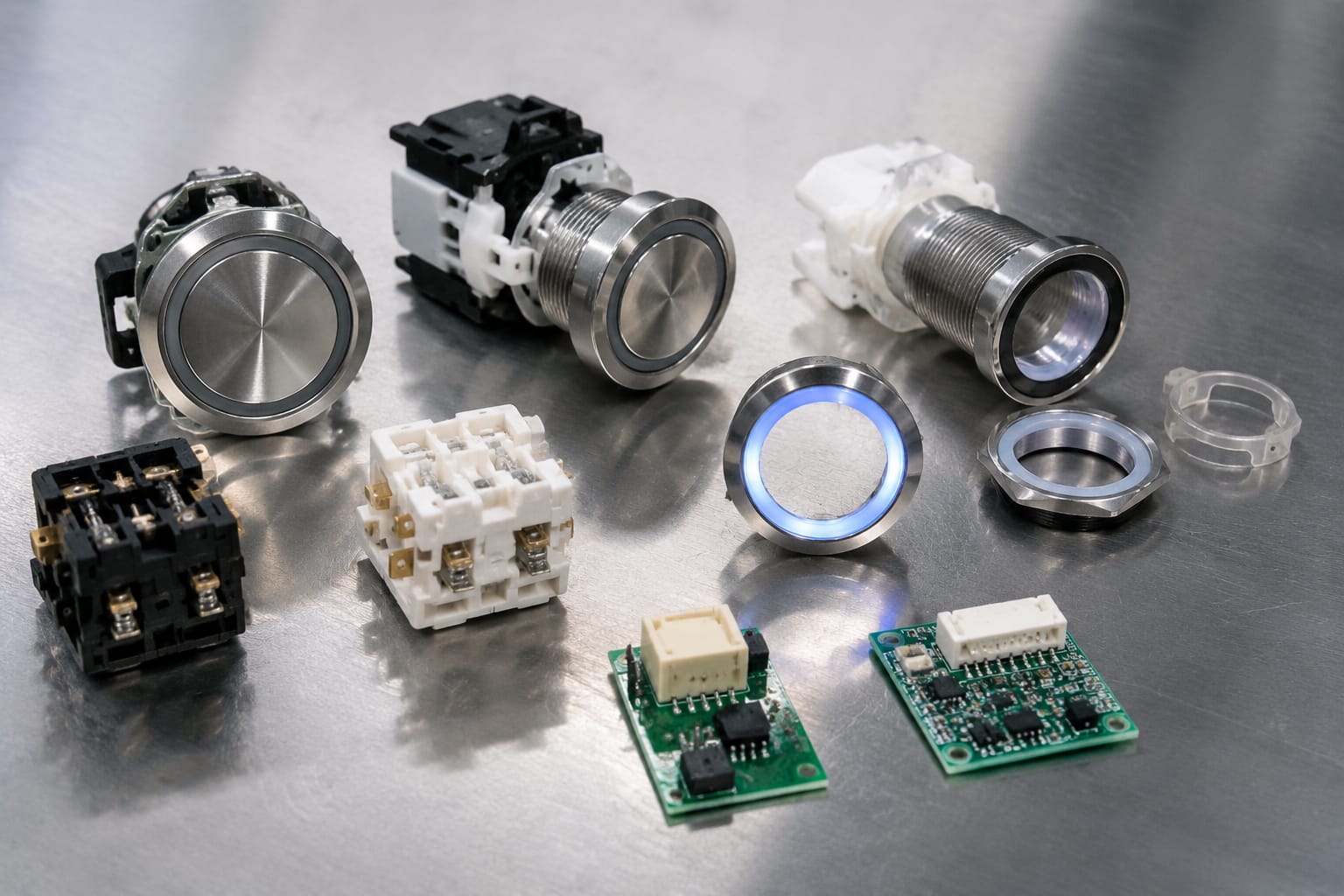
The panel type and elevator configuration provide the context needed to narrow down compatible parts. Begin with the information available on site, but do not rely on a single identifier when selecting a replacement.
Record the following:
- Elevator manufacturer and the branding visible on the fixture
- Elevator model, controller designation, or modernization project information when available
- Car operating panel, hall station, or destination fixture location
- Floor served and whether the landing is a terminal floor
- Button function, such as floor call, door open, or up call
- Number of buttons and display modules in the panel
- Panel finish and fixture family, if the original must match visually
- Any part number, revision, or label on the button, circuit board, or rear housing
A visible KONE logo can help establish the fixture family, but it does not confirm that every component is original or that a current replacement shares the same configuration. Buildings are frequently modernized in stages. A car panel may have been updated while landing stations remain older, and a previously repaired station may contain a substitute component.
Also distinguish a button-level failure from a panel-level problem. If one button is physically damaged, sticks, has a broken lens, or fails to illuminate while nearby buttons work normally, a button or its local connection may be the likely focus. If multiple buttons, the display, or all illumination fail together, inspect the associated board, power supply, harness, and controller communication path before selecting parts.
Do not use the elevator’s serial information as a substitute for examining the removed component. It is useful context, but the installed fixture and board identifiers are usually more decisive for parts matching.
Match Button Dimensions and Mounting
Physical compatibility is the first practical screen. A button that has the correct icon but does not fit the panel cutout, align with the bezel, or retain securely is not a usable replacement.
Measure the original component after safely removing it according to the site’s work procedures. Use calipers where possible and document measurements in inches or millimeters. The most useful dimensions are:
- Visible button or lens width and height
- Overall rear-body width and height
- Panel cutout width and height
- Depth behind the faceplate
- Bezel dimensions and shape
- Retaining clip, screw-tab, or bracket locations
- Spacing between terminals, pins, or connector position
- Distance to adjacent buttons, displays, or internal supports
Button geometry matters. Round buttons, square buttons, rectangular rocker-style controls, and flush capacitive-style interfaces can look similar in catalog photos at a glance but use entirely different mounting systems. Even a small difference in cutout size or body depth can prevent installation.
Check the Retention Method
Identify how the original is held in place:
- Snap-in tabs or spring clips
- A threaded collar or retaining nut
- Screws through a rear bracket
- A button module mounted to a circuit board
- An integrated button-and-board assembly
Do not modify the panel cutout or force retaining clips simply to fit a near-match. Altering the fixture can create alignment issues, reduce retention, interfere with other components, and complicate future service. If the original button is no longer available, evaluate a complete compatible fixture conversion only after confirming its electrical and controller compatibility.
Confirm the Marking and Function
Match the button marking to its assigned function. A floor label, Braille marking, arrow direction, door icon, and emergency-related marking must be appropriate for the original position and intended use. The same physical button family can be fitted with different legends, and a visually compatible face may be functionally wrong.
When replacing a landing button, also confirm whether the station needs an up call, a down call, or both. A terminal landing often has one travel-direction call only, while an intermediate landing commonly has separate up and down controls.
Check Illumination Voltage and Color
Illuminated elevator buttons may use LEDs, lamps, or integrated electronic lighting. Match the original illumination arrangement and confirm its required voltage before installation.
The button’s illumination can serve different purposes:
- Constant backlighting to make the button visible
- A registered-call indication after a passenger presses the button
- Direction or status indication in a landing fixture
- A color-coded signal associated with the fixture design
Never assume the light source or voltage based only on the lens color. A white, red, amber, blue, or green appearance may come from the lens, a colored LED, a board-controlled lighting circuit, or a combination of these.
Check for markings on the original button or board that identify voltage, polarity, LED type, or terminal assignments. If no marking is visible, inspect the wiring diagram, controller documentation, or the working neighboring button only where the comparison is safe and meaningful. The fixture board may supply and control the illumination rather than the button itself.
A replacement with the wrong electrical requirements can cause no illumination, incorrect brightness, erratic registration indication, or damage to a circuit. Likewise, replacing a momentary illuminated button with a non-illuminated version can leave the elevator operational but create an incomplete and confusing user interface.
Color should be matched for functional and visual consistency, but it is not a sufficient compatibility check. Confirm:
- The button’s lighting method.
- Input or operating voltage.
- Polarity or pin assignment, where applicable.
- Whether illumination is controlled locally or by the board.
- The original lens and registered-call indication behavior.
If the lighting issue affects multiple positions, test the fixture’s shared illumination supply and board output before replacing several buttons.
Compare Button and Call-Board Codes
Part numbers, board codes, revisions, and connector labels are among the most valuable identifiers for KONE elevator button replacement. Record every readable code, even if it does not appear to be the ordering number.
A button may carry a molded housing code, while the meaningful service identifier is printed on the board it connects to. Conversely, a board number may identify a family with multiple button configurations. Compare codes as a group with the physical details and function of the component.
For each code, document:
- Full number or alphanumeric sequence
- Revision level or suffix
- Barcode label information
- Manufacturer marking
- Board position label, such as button, display, call, or interface
- Date or production code, when present
- Whether the code is on the button, harness, PCB, or panel frame
Do not omit suffixes. A revision or option suffix can indicate a changed connector, firmware relationship, illumination type, layout, or function. A close base number is a reason to investigate further, not proof of interchangeability.
Landing fixtures often combine call controls and displays on the same assembly or in closely related modules. When troubleshooting these units, compare the original against a compatible KONE call display board based on its complete board code, display type, connector locations, and station role. For fixtures using an LCD-based call interface, use the original LCD layout and board identifiers to evaluate KONE LCD display call-board parts rather than ordering from the screen size alone.
Why Board Revision Matters
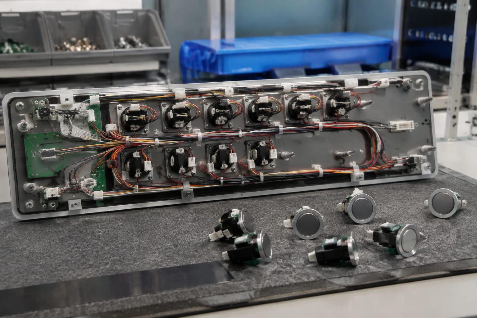
A replacement board can have the same general layout but a different revision. The later version may be approved only for certain fixture generations or require a corresponding harness, software setup, or controller configuration. Confirm interchangeability with technical documentation or a qualified supplier before treating revision changes as direct replacements.
Where the suspected failure is a board, inspect the entire assembly. Loose connectors, moisture damage, corrosion, cracked solder joints, damaged button contacts, or a failed display can produce symptoms that appear to be a simple bad pushbutton.
Inspect Connectors and Wiring
The rear connection is just as important as the front-face match. Inspect the original button and its cable or board interface before ordering and again before applying power after replacement.
Identify whether the component uses:
- Individual spade or screw terminals
- A plug-in harness connector
- Pin headers on a PCB
- A flexible ribbon cable
- Soldered leads
- Direct contact pads against a board
- A multi-button membrane or integrated panel assembly
Photograph the connector straight on and from the side. Count pins, note keyed sections, record wire colors where present, and identify the latch orientation. Do not use wire color alone to determine function; wiring colors can vary by fixture generation, prior repair, or harness source.
Inspect for Damage Beyond the Button
Look for conditions that can cause a repeat failure or a false diagnosis:
- Bent, recessed, or oxidized pins
- A partially seated connector latch
- Pinched harnesses behind the panel
- Strained wires at the button or board edge
- Moisture intrusion in landing fixtures
- Loose panel grounding or mounting hardware
- Damage caused by cleaning fluid or physical impact
Disconnecting or reconnecting electronics with power applied can damage components or create faults. Follow the equipment documentation, site lockout procedures, and applicable safety practices. Elevator systems are safety-critical; diagnostic work that involves controller circuits, safety functions, emergency communication, or uncertain wiring should be handled by qualified elevator personnel.
Test Operation After Replacement
A replacement is complete only after the control, indication, and related panel functions have been tested. Conduct testing according to the maintenance procedure for the equipment and the component replaced.
For an individual car button, verify:
- The button sits flush and returns correctly after pressing.
- The intended floor or function registers.
- The registered-call light behaves as expected.
- Adjacent buttons and display functions still operate.
- The panel can be reassembled without pinching wires or binding the button.
For a landing call button, verify:
- The correct direction can be selected.
- The call indication behaves correctly.
- The call is received by the system.
- The hall display or lantern remains functional, if part of the same fixture.
- Both directions work correctly on non-terminal floors.
Test only under controlled maintenance conditions and use normal facility procedures for returning the elevator to service. For boards and communication-based fixtures, a physical replacement may require configuration, addressing, or controller-level verification. Do not assume that a powered display proves that every call function is communicating correctly.
Record the installed part number, revision, location, date, observed symptom, and test result. This gives future technicians a useful maintenance history and helps identify repeated fixture or wiring problems.
Information to Send a Parts Supplier
A clear parts request allows a supplier to assess compatibility without relying on a vague description such as “KONE button needed.” The following package is usually enough to begin an accurate review:
- Manufacturer branding and elevator model or controller information, if available
- Whether the part is for a car operating panel or a landing station
- Floor location and button function
- Clear front and rear photos of the original component
- Photos of the full panel or station for layout context
- Every visible part number, board code, and revision
- Button face, lens color, and required legend or symbol
- Button, cutout, bezel, and depth measurements
- Mounting method and connector photos
- Pin count, keying, and harness details
- Illumination type, voltage marking, and observed lighting behavior
- Whether the problem affects one control or several fixture functions
- Quantity needed and whether matching appearance across a group of fixtures is required
Include the original component whenever practical for technical comparison, but do not delay documenting it. Photos taken before disassembly often preserve details that are difficult to reconstruct later.
Kelevator supplies multi-brand elevator spare parts for B2B importers, distributors, maintenance contractors, modernization companies, and OEM buyers. For a practical compatibility review, provide the part information above and ask the supplier to confirm the physical, electrical, and board-level match before ordering.
Frequently Asked Questions
Can I replace a KONE elevator button with one that has the same size and icon?
Not reliably. The visible size and icon address only part of the match. Confirm the panel cutout, rear-body depth, mounting arrangement, connector, illumination requirements, and associated board compatibility before using a replacement.
Does a matching board number guarantee compatibility?
Not always. Check the complete number, including revision and suffix, along with the connector layout, fixture function, display arrangement, and installed system configuration. Similar board numbers can represent related but non-interchangeable versions.
Why does a new button not light up even though it registers a call?
The button may have the wrong illumination voltage or polarity, the fixture board may control lighting separately, or the shared lighting output or wiring may have a fault. Confirm the original lighting arrangement before replacing the button again.
Should I replace the button or the call board?
Replace the button when the fault is isolated to its mechanism, lens, contact, or local illumination and the board tests correctly. Investigate the call board, harness, and power path when several buttons, display functions, or indicators fail together.
Related product references
For practical catalog examples related to this topic, review COB Car Button Board KONE elevator parts, Call Display Board KONE elevator parts lift accessories, and LCD Display Call Board KONE elevator parts lift accessories. Confirm the exact model, dimensions, ratings, and connectors before ordering.