
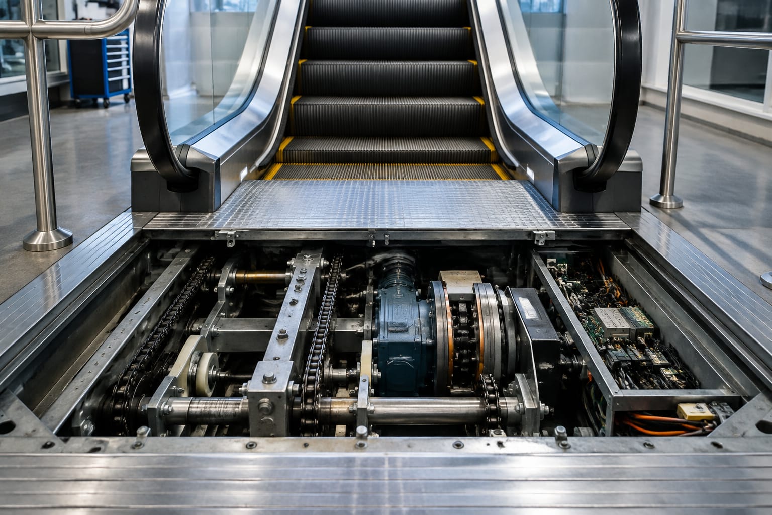
Escalator equipment is an interconnected set of mechanical, electrical, and safety systems that moves passengers while monitoring for unsafe conditions. The key assemblies are the step band and chain system, tracks, handrails, drive machinery, brakes, controller, and safety devices.
For maintenance teams and parts buyers, the practical priority is not simply identifying a failed component. It is confirming the correct part against the escalator’s manufacturer, model, serial information, revision, mounting arrangement, electrical rating, and the condition of related components. A replacement part that appears similar can create fitment, performance, or safety issues.
Main Escalator Systems at a Glance
An escalator can be viewed as five working systems. Each depends on the others, so troubleshooting should account for the whole operating path rather than treating a fault code or worn item in isolation.
| System | Primary function | Typical components | Maintenance focus |
|---|---|---|---|
| Step band | Carries passengers between landings | Steps, step chains, sprockets, axles, rollers, tracks | Alignment, wear, lubrication where specified, broken or damaged parts |
| Handrail | Provides a moving handhold synchronized with steps | Handrail belt, drive wheel, rollers, tensioning carriage, guides | Speed relationship, belt condition, tracking, tension |
| Drive system | Produces and transfers motion | Motor, gearbox or gearless drive, drive chain or coupling, main shaft | Noise, heat, vibration, oil condition, coupling and chain wear |
| Braking system | Stops and holds the escalator under defined conditions | Main brake, auxiliary brake, brake coils, switches, linkages | Brake opening and stopping performance, adjustment, electrical actuation |
| Control and safety system | Commands operation and detects hazardous conditions | Controller, relays, VFD where used, sensors, safety switches, wiring | Fault history, contact condition, functional testing, damaged wiring |
The exact architecture differs by manufacturer, generation, installation type, and modernization history. A unit may use different brake arrangements, controller families, sensor designs, or handrail mechanisms even within the same product line. Site verification remains essential.
Steps, Chains, Tracks, and Comb Plates
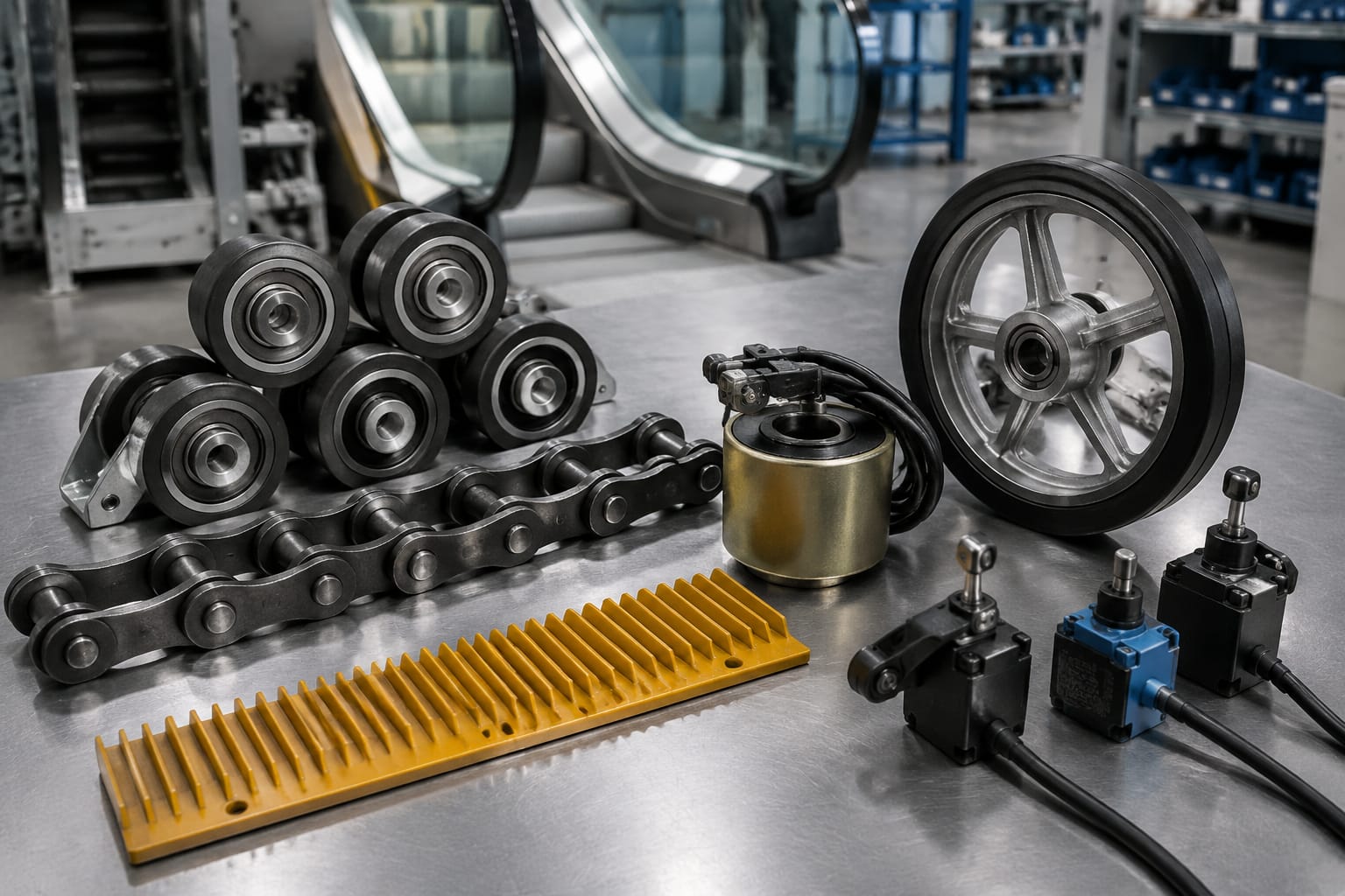
The step band is the passenger-carrying mechanism. Individual steps circulate around the truss, remain level through the incline, and flatten at each landing to pass beneath the comb plate. It is a highly loaded assembly, and small alignment errors can develop into visible or audible operating problems.
Steps and step axles
A step includes treads, risers, wheels or rollers, axles, and chain attachments. Damaged treads, cracked castings, worn wheel surfaces, or loose hardware can affect passenger footing and step tracking. Replacement steps should be matched carefully for dimensions, tread geometry, roller configuration, axle arrangement, material, finish, and chain connection details.
Do not assume that a step from a visually similar escalator is interchangeable. A mismatched step can interfere with adjacent steps, guides, comb plates, or skirt panels.
Step chains and sprockets
Step chains transmit motion through the step band. Wear can occur at pins, bushings, rollers, links, attachments, and sprocket teeth. Chain elongation, damaged rollers, poor lubrication where required, and sprocket wear may contribute to uneven movement, noise, vibration, or tracking problems.
Maintenance personnel commonly inspect for:
- Uneven chain tension between left and right sides
- Damaged, seized, or excessively worn chain rollers
- Wear patterns on sprocket teeth
- Loose or damaged step-chain attachment hardware
- Evidence of rubbing against guides or other fixed components
- Lubrication condition based on the OEM maintenance instructions
Chain adjustment must follow the manufacturer’s specified method and limits. Over-tightening can raise loads and accelerate wear; under-tensioning can create tracking and engagement problems.
Tracks and guide rails
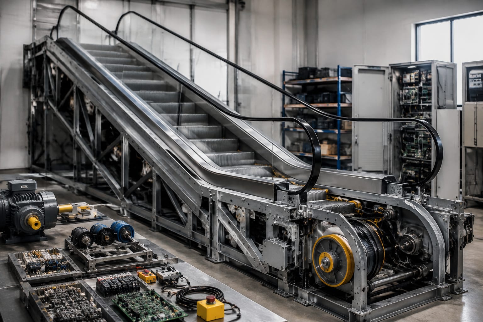
Tracks guide step wheels and step-chain rollers along the escalator path. Wear, contamination, loose supports, incorrect alignment, or damaged joints can lead to a rough ride, noise, wheel damage, or step movement abnormalities.
Track work requires special care because it affects the geometry of the complete step band. Before replacing rollers or steps repeatedly, inspect whether the underlying track condition is producing the wear pattern.
Comb plates and impact protection
Comb plates bridge the landing floor to the moving steps. Their teeth mesh with the step tread grooves, helping reduce the opening at the landing interface. Damaged, missing, or poorly seated comb segments can create a significant safety concern.
Inspection points include:
- Broken, bent, or missing comb teeth
- Step tread damage near the comb interface
- Secure mounting and correct seating
- Foreign material accumulation
- Proper operation of comb-impact detection devices where fitted
Do not file, reshape, or improvise comb teeth to make a part fit. Use the correct component and investigate why damage occurred, especially if it recurs.
Handrail Drive and Tensioning Parts
The handrail system should move in the same direction and at a closely matched speed to the steps. It typically includes a reinforced rubber or synthetic belt, drive wheel, rollers, guides, inlet brushes or guards, and a tensioning system.
A handrail that slips, wanders, runs noticeably out of sync, or shows surface damage should be evaluated promptly. The issue may originate in the belt itself, but it can also result from worn drive components, incorrect tension, contaminated surfaces, guide problems, or a failing handrail speed-monitoring device.
Handrail belts and drive wheels
Common handrail wear indicators include cracking, glazing, hardening, frayed edges, separation, loss of grip, and abnormal surface wear. The correct replacement handrail depends on its profile, dimensions, reinforcement design, length, splice method where applicable, and compatibility with the drive system.
Drive wheels need adequate traction and correct alignment. Contamination from lubricants or cleaning products can reduce grip. Excessive wear or a damaged drive surface can cause intermittent slipping even when the handrail itself appears serviceable.
Tensioning carriage, rollers, and guides
The tensioning assembly maintains the handrail’s working tension as it stretches in service. Rollers and guides route the belt through the balustrade and around the landing sections. Worn bearings, seized rollers, loose guides, or poor tracking can damage handrail edges and increase drag.
When assessing handrail parts, verify:
- Handrail profile and dimensions
- Drive-wheel arrangement and rotation direction
- Tensioning travel and spring or weight configuration
- Roller diameters, mounting points, and bearing type
- Guide material, location, and attachment method
- Any related safety switches or speed-monitoring components
Replacing only the visibly worn roller may not solve a tracking issue if the guide path or tensioning mechanism is misaligned.
Main and Auxiliary Brakes
Escalator braking systems are safety-critical assemblies. Their design varies, but they generally include a main service brake and, on applicable equipment, an auxiliary or additional braking function that responds to defined abnormal conditions.
The main brake is normally associated with the drive machinery and brings the escalator to a stop when power is removed or a stop command is initiated. An auxiliary brake may act independently or through a separate mechanism if overspeed, unintended direction of travel, or another monitored condition occurs.
What to inspect on brake assemblies
Brake inspection and adjustment should be performed by qualified personnel using the manufacturer’s procedures and applicable local requirements. Important checks commonly include:
- Brake linings, drums, discs, or friction surfaces for wear or contamination
- Brake coil condition and correct electrical rating
- Air gap, spring force, linkage condition, and release movement
- Fasteners, pins, pivots, and mechanical clearances
- Brake-monitoring switch operation
- Evidence of overheating, drag, or delayed release
- Functional stopping performance under the required test procedure
A brake that is noisy, slow to release, or apparently functional should not be assumed acceptable without inspection. Friction material contamination, incorrect adjustment, coil problems, and worn mechanical components can affect performance.
For buyers replacing electrical brake components, an escalator auxiliary brake controller must be matched to the applicable system rather than selected solely by appearance. Confirm the original part number, controller revision, input and output characteristics, connector arrangement, and the equipment documentation.
Likewise, a brake board for applicable Otis escalator systems should be verified against the specific controller and installation. Board numbers alone can be insufficient when revisions or system configurations differ.
Motors, Drives, and Controllers
The drive system supplies motion to the step band and handrails. It commonly includes an electric motor, transmission or gearbox where used, coupling or drive chain, main shaft, bearings, and a brake. The controller manages starting, stopping, direction, monitoring, and fault response.
Motor and mechanical drive components
A motor problem may present as overheating, repeated overload trips, abnormal current draw, poor starting, unusual noise, or vibration. However, a motor fault can also be a symptom of mechanical resistance elsewhere in the escalator.
Before replacing a motor, evaluate the load path:
- Inspect the step band, handrails, and drive train for binding or excessive drag.
- Check bearings, gearbox condition, chains, couplings, and sprockets as applicable.
- Review controller faults and electrical supply conditions.
- Confirm the motor nameplate data, mounting, shaft details, brake interface, and connection configuration.
- Use the OEM procedure for insulation, current, and operational tests.
Gearboxes and mechanical transmissions deserve condition-based inspection for leaks, lubricant condition, bearing noise, gear noise, mounting security, and temperature trends. Lubricant selection and change intervals must follow the equipment manufacturer’s requirements; a generic oil substitution can be unsuitable.
Controllers, relays, and drive electronics
The escalator controller receives inputs from safety devices and controls the motor, brake, operating direction, and optional functions such as auto-start or reduced-speed operation. Depending on equipment design, it may include relays, contactors, a variable-frequency drive, programmable controls, or dedicated monitoring boards.
When evaluating a controller fault, record the fault message, operating state, recent maintenance work, affected safety circuit, and any intermittent conditions. Resetting a trip without identifying the cause can return equipment to service with an unresolved safety or mechanical issue.
For brake-related repairs, the additional brake electromagnetic coil must be checked for the correct voltage, duty characteristics, dimensions, mounting, and corresponding brake assembly. Coil compatibility is an electrical and mechanical question.
Safety Switches and Sensors
Safety switches and sensors allow the controller to detect conditions that require stopping the escalator or preventing startup. The exact list varies by design, but common protective devices monitor the comb plate, step band, handrail entry, handrail speed, drive chain, brake condition, overspeed, unintended movement, and access panels.
These components should be treated as part of a safety circuit, not as isolated convenience switches. Bypassing, permanently jumpering, or substituting an unverified sensor can defeat intended protection and create compliance exposure.
Common device categories
| Device category | Typical purpose | Practical inspection concern |
|---|---|---|
| Comb-impact switch | Detects displacement or impact at the comb plate | Secure actuation, correct reset, no damage or obstruction |
| Step or chain monitoring switch | Detects abnormal step-band or chain condition | Correct position, intact actuator, wiring condition |
| Handrail speed monitor | Detects handrail movement outside the allowed relationship to steps | Sensor gap, target condition, drive traction, calibration requirements |
| Brake switch | Confirms brake position or release state | Reliable actuation, alignment, contact condition |
| Overspeed or unintended-movement device | Detects abnormal travel behavior | Mechanical condition, electrical interface, functional test per procedure |
| Skirt or entry-area protection | Detects conditions near passenger interfaces where fitted | Cleanliness, physical damage, correct operation |
Moisture, dust, vibration, loose hardware, damaged cable insulation, and poor connector contact can all create intermittent safety-circuit faults. Inspection should include the physical device, mounting hardware, actuator or target, connector, cable routing, and controller input history.
Common Wear and Inspection Points
A preventive maintenance program should focus on the components that carry load, produce motion, protect passenger interfaces, or initiate a shutdown. The appropriate intervals and tasks are determined by the OEM documentation, operating environment, use level, service history, and applicable code requirements.
In the United States, escalation equipment maintenance and inspection obligations can also involve the authority having jurisdiction and applicable editions of ASME A17.1/CSA B44 and local rules. The installed equipment documentation and jurisdictional requirements should govern the maintenance program.
High-value routine checks
Use a documented inspection process that includes at least the following areas:
- Step treads, risers, wheels, axles, and step-chain attachments
- Step-chain condition, sprockets, tension, and track alignment
- Comb plates, comb teeth, impact devices, and landing interfaces
- Skirt panels and clearances as specified by the equipment manufacturer
- Handrail surface condition, tracking, entry guards, drive traction, and tension
- Motor, gearbox, bearings, couplings, chains, and unusual noise or vibration
- Main and auxiliary brake condition, switches, and approved functional tests
- Controller cabinet cleanliness, cooling, terminals, relays, contactors, and fault logs
- Safety switches, sensors, cable condition, and secure mounting
- Emergency stop devices, access covers, and lighting where applicable
Common mistakes that increase downtime
Several maintenance shortcuts create recurring problems:
- Replacing parts without identifying the original cause of wear
- Ordering from a photo without confirming the part number and revision
- Mixing left-hand and right-hand components
- Ignoring the escalator’s direction, inclination, width, and landing configuration
- Adjusting brake or chain settings outside OEM procedures
- Treating intermittent sensor faults as nuisance trips
- Failing to inspect mating parts when replacing chains, rollers, or friction components
- Using unapproved lubricants, cleaners, or electrical substitutions
A condition record is useful for spotting repeated defects. Track fault codes, parts replaced, measurements, noise reports, lubricant observations, and recurring wear locations. This creates a stronger basis for planned parts procurement and modernization decisions.
Sourcing Escalator Replacement Parts
Successful replacement-part sourcing begins with identification, then compatibility, then commercial evaluation. The lowest unit price is not meaningful if the part does not match the installed equipment or if related hardware is missing.
Provide a supplier with as much of the following as possible:
- Escalator manufacturer, model, serial number, and installation information
- Original part number and any revision, date code, or marking
- Clear photographs of the part, labels, connectors, mounting points, and surrounding assembly
- Dimensions and electrical nameplate data where relevant
- Equipment location within the escalator, such as upper landing, lower landing, drive unit, or handrail system
- Whether the part is left-hand, right-hand, directional, or position-specific
- Details of modifications, prior modernization work, or substituted components
- The reason for replacement and any associated fault code or observed symptom
Questions to ask before placing an order
Confirm whether the offered part is intended for the exact installed application and whether it includes needed accessories such as connectors, brackets, hardware, or programming-related items. For electrical parts, verify voltage, current or power ratings, terminal layout, software or board revision where applicable, and safety-circuit role.
For mechanical parts, verify material, dimensions, tooth count, pitch, bore, bearing specification, mounting orientation, surface finish, and required mating components. Ask whether the quoted item is a complete assembly or only a subcomponent.
Kelevator supplies multi-brand elevator spare parts for B2B importers, distributors, maintenance contractors, modernization companies, and OEM buyers. For an escalator-parts inquiry, sending complete identification details and installed-equipment photos helps establish whether a component is appropriate before procurement.
The practical next step is to build a site-specific parts record from the equipment documentation and recent service findings. Use it to verify each replacement against the installed escalator before ordering or fitting the part.
Related product references
For practical catalog examples related to this topic, review Escalator auxiliary brake controller lift parts elevator accessories, Escalator 508 Brake Board OTIS elevator parts lift accessories, and Escalator additional brake electromagnetic coil lift accessories elevator spare parts. Confirm the exact model, dimensions, ratings, and connectors before ordering.