
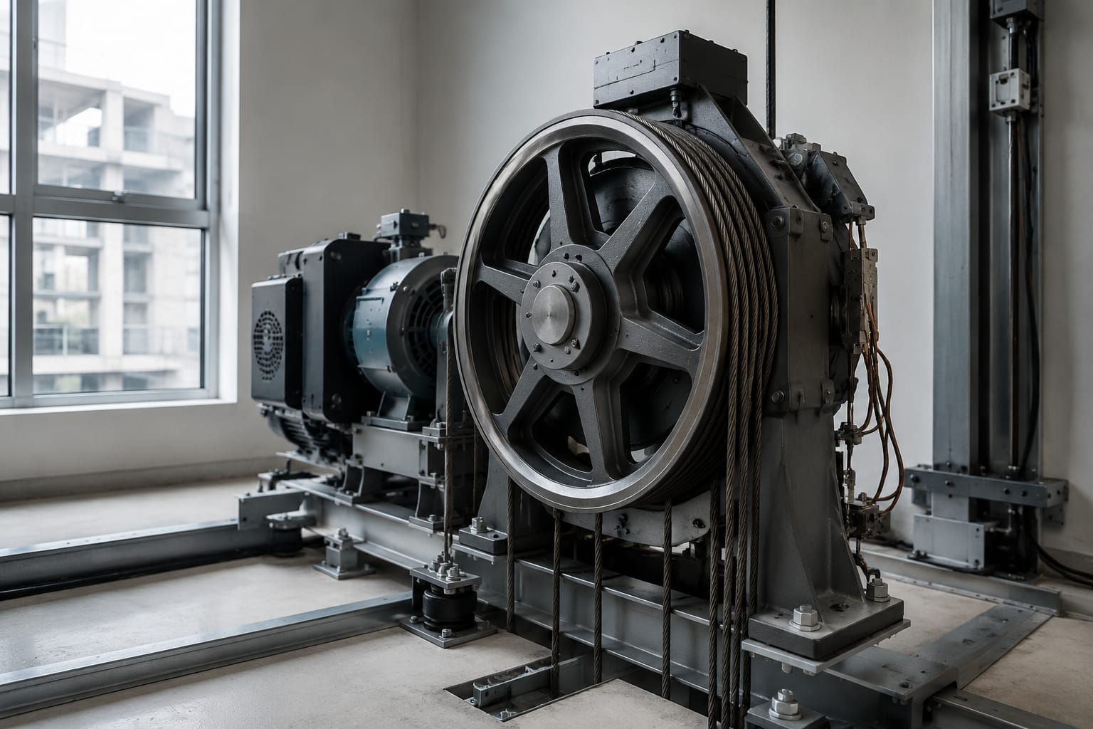
An elevator traction sheave transfers motor torque to the elevator suspension system through the friction, or traction, developed at its grooves. A replacement is not interchangeable simply because its outside diameter looks similar. The groove geometry, suspension medium, shaft bore, keyway, mounting arrangement, and machine compatibility must all match the original design.
Wear in an elevator traction sheave can reduce grip, accelerate rope or belt damage, create uneven loading, and contribute to ride and leveling problems. The practical approach is to inspect the sheave and suspension medium together, record the critical dimensions, and verify the machine and system documentation before ordering.
How a traction sheave works
A traction machine turns the traction sheave, while the elevator car and counterweight are suspended on opposite sides of the sheave. The ropes or belts pass over the grooved rim. Rotation moves the suspension medium and, in turn, raises or lowers the car.
The sheave does not normally drive the ropes or belts through positive mechanical engagement like a gear. Instead, it relies on friction between the groove surface and the suspension medium. The available traction depends on the system design, including:
- Groove profile and groove condition
- Sheave diameter
- Rope or belt material, construction, and condition
- Wrap angle around the sheave
- Car-to-counterweight loading balance
- Contamination from oil, moisture, rust, or cleaning products
- Equal tension across all ropes or belts
A groove that is too worn, polished, contaminated, or incorrectly shaped changes the contact conditions. The result may be reduced traction under demanding load conditions or excessive abrasion during normal operation.
Because traction, braking, overspeed protection, suspension, and control functions interact, a sheave replacement should be treated as a system-specific maintenance or modernization task. The original equipment documentation and applicable code requirements should govern final acceptance.
Steel-rope and steel-belt applications
Traction sheaves are designed around a specific suspension medium. Steel wire ropes and coated steel belts have different dimensions, contact surfaces, bending characteristics, and manufacturer-defined requirements. A sheave intended for one should never be selected solely by matching its nominal diameter to another.
Steel wire rope sheaves
Conventional traction systems use multiple round steel wire ropes. Their sheaves have individual grooves sized and profiled for the specified rope diameter and construction. The grooves support the rope while producing the friction needed for traction.
Key considerations for rope applications include:
- Nominal rope diameter and permitted dimensional tolerance
- Number of ropes and groove count
- Groove center-to-center pitch
- Groove profile, such as round, undercut, or V-based geometry
- Rope lay, construction, and coating where specified
- Sheave material and surface condition
- Rope tension equalization
A rope can look serviceable while its grooves are no longer consistent. Uneven groove wear can cause one or more ropes to carry more load, which increases wear across the entire suspension set.
Steel belt sheaves
Steel-belt suspension systems use flat, often coated belts with embedded steel cords. Their traction sheaves have profiles engineered for the belt width, thickness, cord layout, coating, and intended contact pattern. The belt generally rides in a matched channel or groove configuration rather than a round-rope groove.
For a belt-driven installation, verify:
- Belt manufacturer and exact belt designation
- Belt width, thickness, and cord configuration
- Number of belts and groove count
- Groove/channel width and depth
- Pulley diameter specified for the belt system
- Permitted belt contact surfaces and coatings
- Machine model and original system arrangement
For examples of system-specific parts, compare the published product details for an ID steel-belt traction sheave with the requirements of the machine it is intended to serve. Product naming alone is not a compatibility confirmation.
Do not substitute between suspension types
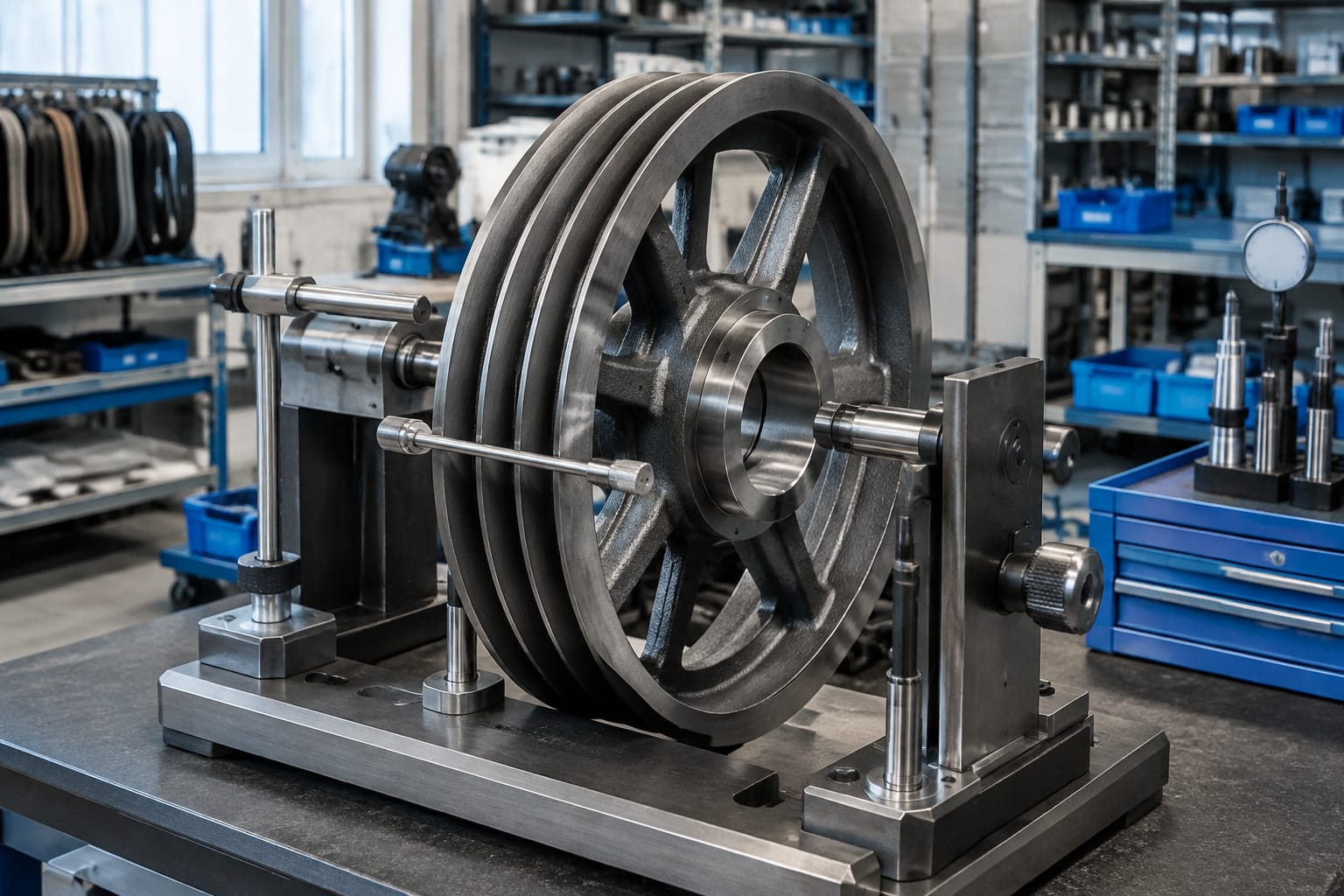
A round-rope traction sheave and a steel-belt traction sheave may both be called pulleys or sheaves, but they are not generic substitutes. Attempting to run belts on rope grooves, or ropes in belt channels, can damage the suspension medium and compromise traction. Retain the original suspension type unless a complete, engineered modernization design explicitly changes it.
Groove profiles and traction conditions
The groove profile determines how the rope or belt contacts the sheave. It influences traction, contact pressure, bending behavior, and wear rate. The correct profile is the one specified for the installed machine and suspension system, not necessarily the profile that appears to provide the strongest grip.
For wire ropes, common concepts include round-bottom grooves, undercut grooves, and V-shaped or modified V-shaped grooves. The exact geometry varies by manufacturer and application.
| Groove condition or profile issue | Likely effect | Inspection focus |
|---|---|---|
| Uniform, correctly matched groove | Predictable traction and support | Confirm against the original specification |
| Polished or glazed groove surface | Friction characteristics may change | Check for slipping history and contamination |
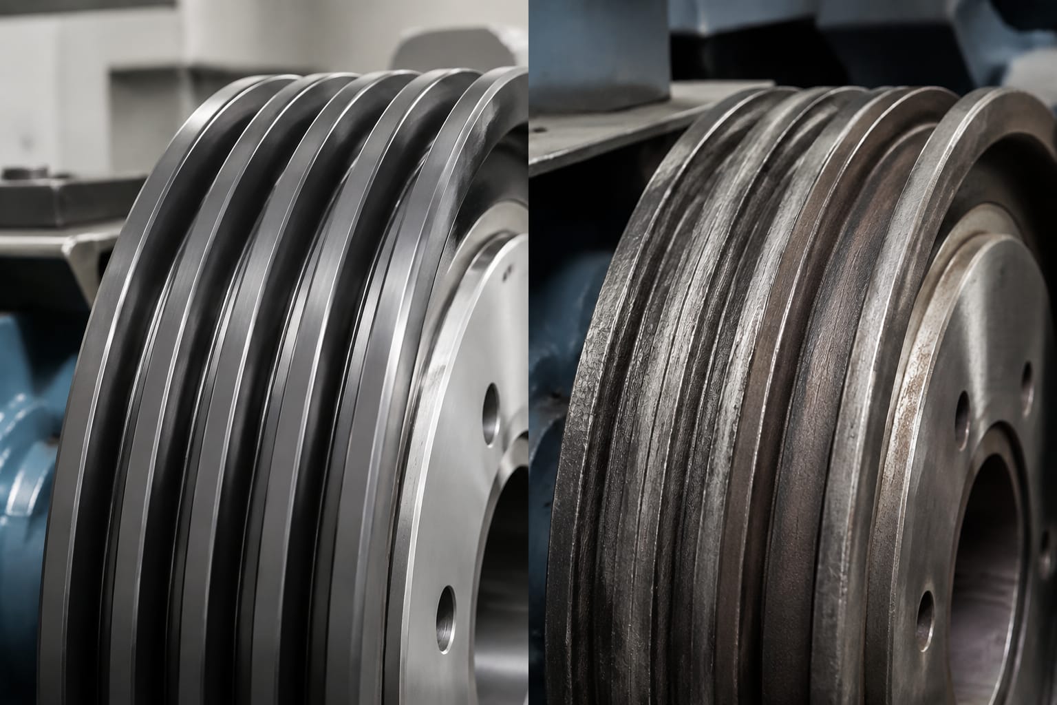
| Worn groove bottom | Rope sits deeper and contact geometry changes | Compare groove depth and profile across all grooves |
| Uneven groove wear | Unequal rope loading and accelerated rope wear | Check tension and rope seating |
| Sharp edges, burrs, or corrosion | Abrasion and coating or wire damage | Inspect groove surfaces by sight and touch, with proper lockout |
| Incorrect replacement profile | Unpredictable traction and suspension wear | Verify part drawing and suspension-medium specification |
More aggressive groove geometry can increase traction, but it can also raise localized contact pressure and rope wear. That tradeoff is designed into the machine. Field modification, re-grooving, or machining should not be assumed acceptable without the machine manufacturer’s approved limits and a qualified evaluation.
Contamination deserves equal attention. Oil, grease, water, rust products, paint, and unsuitable cleaners can alter traction or damage belt coatings. Correct the source of contamination before installing a new sheave or suspension set; otherwise, the new components may inherit the same failure mechanism.
Signs of sheave and belt wear
Inspect the traction sheave whenever rope or belt wear is identified, when ride quality changes, during a modernization survey, or at the service intervals required by the maintenance program. A visual inspection is useful, but dimensional checks are needed to determine whether wear is uniform and within the manufacturer’s allowable limits.
Common signs of traction sheave wear include:
- Grooves with a visibly flattened, deepened, or asymmetric profile
- Different seating depths among ropes in adjacent grooves
- Highly polished groove surfaces or localized scoring
- Rust, pitting, cracking, chips, or raised material at groove edges
- Rope dust, metallic debris, or damaged belt coating near the machine
- Repeated difficulty maintaining equal rope tension
- Noise, vibration, or irregular rope travel at the sheave
- Traction loss symptoms, including unintended relative movement under conditions that should maintain grip
For steel belts, also inspect for coating damage, exposed cord indications, edge wear, debris embedded in the coating, and nonuniform tracking. Follow the belt manufacturer’s inspection and retirement criteria. A belt’s external coating condition is important, but it does not replace the required inspection methods for the complete belt construction.
Do not diagnose every traction issue as a worn sheave. Poor rope tension, contamination, incorrect suspension adjustment, brake issues, loading conditions, or installation errors can create similar symptoms. The goal is to identify the underlying condition before specifying parts.
Measure diameter, grooves, and shaft interface
A sourcing package should include actual measurements, photographs, and machine identification, not just a description such as “traction sheave for 8 mm ropes.” That description omits the interface and geometry details that determine whether the part can be installed and operate correctly.
Record the sheave dimensions
Measure with clean, calibrated tools and document the measurement locations. Depending on the design, the essential dimensions include:
- Outside diameter of the sheave
- Pitch diameter or manufacturer-defined working diameter, where applicable
- Face width
- Number of grooves or belt channels
- Groove pitch, measured center to center
- Groove width, depth, and profile
- Rim thickness where accessible and relevant
- Hub length and hub outside diameter
- Overall assembly length
- Directional or offset features
For a worn sheave, take the same groove measurements at multiple locations and across every groove. This identifies whether the wear is uniform. Measurements from one apparently representative groove can hide a tensioning or alignment problem.
Define the shaft and mounting interface
The bore and drive interface are as important as the rim dimensions. Confirm:
- Shaft bore diameter
- Bore type, such as straight, tapered, splined, or another proprietary configuration
- Keyway width, depth, and location
- Key type and keyway orientation
- Threaded retention features, locknut arrangement, or end hardware
- Hub-side orientation and any mounting shoulder
- Set-screw holes, retaining features, or balance provisions
- Required axial position on the shaft
Do not rely on a tape measure for the bore or groove profile when a proper caliper, micrometer, bore gauge, or manufacturer drawing is available. Small dimensional differences can prevent assembly or misplace the sheave relative to the ropes, belts, guards, and adjacent machine components.
Provide useful sourcing evidence
A practical request for quotation or technical review usually includes:
- Clear photos of both sheave faces, the grooves, bore, keyway, and identification marks.
- A dimensioned sketch with units clearly labeled.
- Machine manufacturer, model, serial information, and original part number when available.
- Suspension-medium information, including rope diameter or exact belt designation.
- The reason for replacement, such as groove wear, corrosion, modernization, or damage.
- Information on whether ropes or belts will also be replaced.
When evaluating a round-rope replacement, a product such as this traction steel pulley for elevator applications can be a useful reference point for the type of information a supplier may need. Confirm all dimensions and machine-specific details before treating any listed part as a match.
Check machine and suspension compatibility
The correct elevator traction sheave must fit mechanically and preserve the original traction system design. Confirm compatibility at three levels: the machine, the suspension medium, and the elevator system.
| Compatibility area | What to verify | Why it matters |
|---|---|---|
| Machine | Manufacturer, model, shaft design, mounting method, guard clearance | Prevents installation and alignment problems |
| Sheave geometry | Diameter, groove count, pitch, profile, face width, hub offset | Maintains intended rope or belt travel |
| Suspension medium | Rope diameter and construction, or exact belt designation | Prevents incompatible contact and accelerated wear |
| Suspension arrangement | Number of ropes or belts, reeving, wrap, termination arrangement | Affects load distribution and traction |
| System condition | Tension, alignment, contamination, companion sheaves | Avoids repeating the original failure cause |
| Documentation | Original part number, drawings, approved modernization data | Supports a defensible replacement decision |
Sheave diameter is especially important because it affects the bending imposed on ropes or belts. A smaller diameter is not automatically acceptable even when the part fits the shaft. Likewise, a larger diameter can interfere with the machine frame, guards, rope paths, or adjacent equipment.
Confirm whether the part is the drive traction sheave or another grooved component, such as a deflector, secondary, or compensation sheave. These components may look similar, but their grooves, load cases, bearings, and interfaces can differ.
For systems using Otis steel-belt components, review the fitment information for a traction steel-belt elevator part against the exact machine and belt arrangement. Compatibility should be established from the applicable machine and suspension documentation rather than brand family alone.
Replacement planning and handling
Replacement planning should address the sheave, suspension medium, tooling, adjustment work, and post-installation verification as one job. Installing a new sheave onto worn or mismatched ropes or belts can create accelerated wear, while installing new ropes or belts on a severely worn sheave can damage the new suspension medium early in service.
Before work begins, establish:
- The approved replacement part and revision
- Whether ropes, belts, bearings, keys, retaining hardware, or guards also need replacement
- Lockout, car support, counterweight restraint, and other site-specific safety procedures
- Lifting method and handling capacity for the sheave assembly
- Required torque values, lubricants, sealants, and retention methods from the machine documentation
- The tensioning and alignment process after installation
- Acceptance tests and inspection records required by the maintenance program and local authority
A traction sheave can be heavy and its groove surfaces are precision working areas. Store and move it in a way that avoids dropping, striking, contaminating, or setting it directly on the grooves. Protect the bore, keyway, and machined faces from corrosion and impact damage.
Do not reuse retaining components merely because they appear intact if the manufacturer specifies replacement hardware or a one-time-use locking method. Similarly, do not alter bore dimensions, keyways, grooves, or balancing features in the field without documented approval and the appropriate capability.
Inspection after installation
The installation is not complete when the sheave is mounted. Post-installation inspection confirms that the system runs in the intended plane, the suspension medium seats correctly, and no new source of wear has been introduced.
Check the following before returning the unit to normal service:
- Sheave orientation, axial position, and retention
- Guard and frame clearances through the relevant travel conditions
- Correct rope or belt seating in every groove or channel
- Alignment of the traction sheave with deflector sheaves and rope or belt paths
- Equalized rope tension or the manufacturer-specified belt tension condition
- Absence of rubbing, edge contact, abnormal tracking, or debris generation
- Correct operation during the required inspection and test procedures
- Documentation of installed part identification and baseline measurements
After initial operation, reinspect for seating changes, debris, belt coating marks, rope displacement, unusual noise, or movement of retention hardware. The timing and scope of follow-up checks should follow the machine manufacturer’s instructions, the suspension manufacturer’s criteria, the site maintenance plan, and applicable jurisdictional requirements.
FAQ
Can a traction sheave be replaced without replacing the ropes or belts?
Sometimes, but only after evaluating both components together. If the existing ropes or belts meet their inspection criteria, match the replacement sheave, and have not been damaged by the worn sheave, separate replacement may be appropriate. If groove wear has caused uneven loading, scoring, abrasion, or coating damage, replacing only the sheave may leave a shortened-life suspension system in service.
How do I know whether a groove is too worn?
Use the original manufacturer’s allowable wear limits and a measurement method appropriate to the groove profile. Visual appearance alone is not enough. Compare depth, width, profile, and seating across all grooves, then assess rope or belt condition and tension distribution.
Is the outside diameter enough to identify a replacement sheave?
No. Outside diameter is only one dimension. The groove count and pitch, groove profile, face width, bore, keyway, hub geometry, axial offset, shaft interface, and machine model must also be confirmed.
Can a worn traction sheave be re-grooved?
That depends on the machine design, remaining material, balance requirements, groove specification, and manufacturer approval. Re-grooving changes the contact surface and may affect the sheave’s suitability. Do not assume machining is an acceptable alternative to replacement.
For a replacement decision, assemble the machine identification, suspension details, photos, and measured interface dimensions before comparing parts. Kelevator supplies multi-brand elevator spare parts for B2B buyers, and a complete technical package helps a distributor, contractor, or sourcing team evaluate the correct sheave configuration without relying on visual similarity alone.