
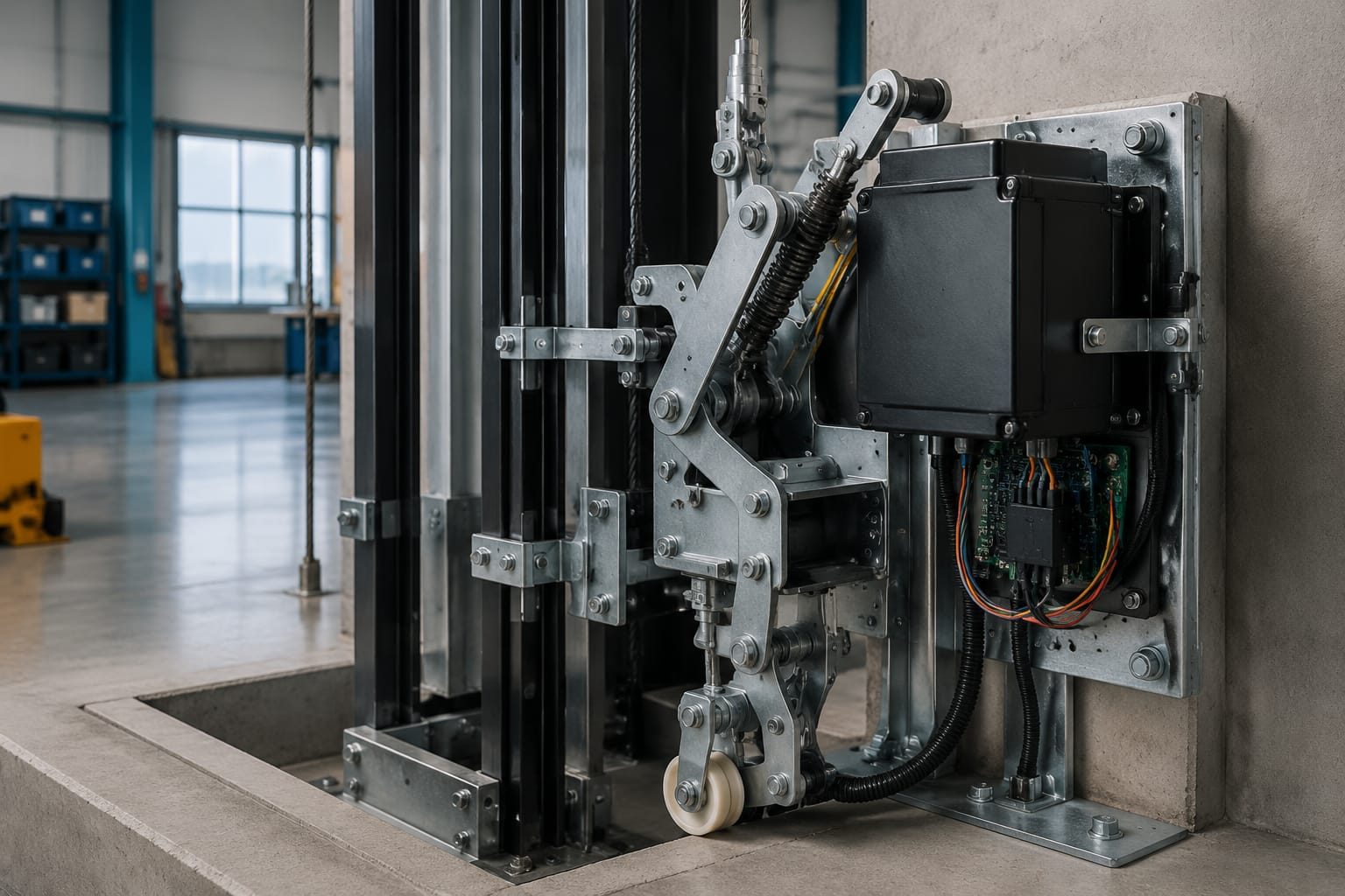
Lift safety gear is the mechanical device that grips the guide rails to stop and hold an elevator car when the safety system detects an overspeed condition or another specified unsafe condition. It is not the normal stopping brake. The machine brake stops routine travel; the safety gear is an emergency protective system designed to act through the governor, governor rope, and car-mounted linkage.
For maintenance and modernization work, the important question is not simply whether a replacement safety gear looks similar. The assembly must match the car configuration, guide rail profile, rated speed, suspension arrangement, governor system, and applicable code requirements. Adjustment, activation testing, and return-to-service documentation should be handled by qualified elevator personnel under the authority having jurisdiction.
How elevator safety gear stops the car
Elevator safety gear is normally mounted at the lower portion of the car frame, often on both sides where the car frame meets the guide rails. During normal operation, the safety gear does not contact the rails with enough force to restrict travel.
When the overspeed governor operates, it grips the governor rope. The rope’s movement then pulls a linkage or actuating mechanism on the car. That linkage drives the safety gear jaws, wedges, rollers, or gripping elements into engagement with the guide rails.
The stopping force is generated at the guide rails, rather than by the hoist machine brake. Depending on the design, the gear may either:
- Clamp the rail very rapidly with little stopping travel.
- Apply progressively increasing friction as the car travels a controlled distance.
- Hold the car in place after the safety gear has engaged.
A properly functioning system relies on more than the safety gear itself. Worn linkage pins, an incorrect governor setting, rope damage, mismatched rails, or improper adjustment can prevent the system from operating as intended.
Safety gear activation is an abnormal event. Once it has operated, the elevator should not simply be reset and placed back in normal service. Qualified personnel need to determine why it tripped, inspect affected components, confirm rail and car-frame condition, and complete the required testing before release.
Governor, rope, linkage, and safety gear
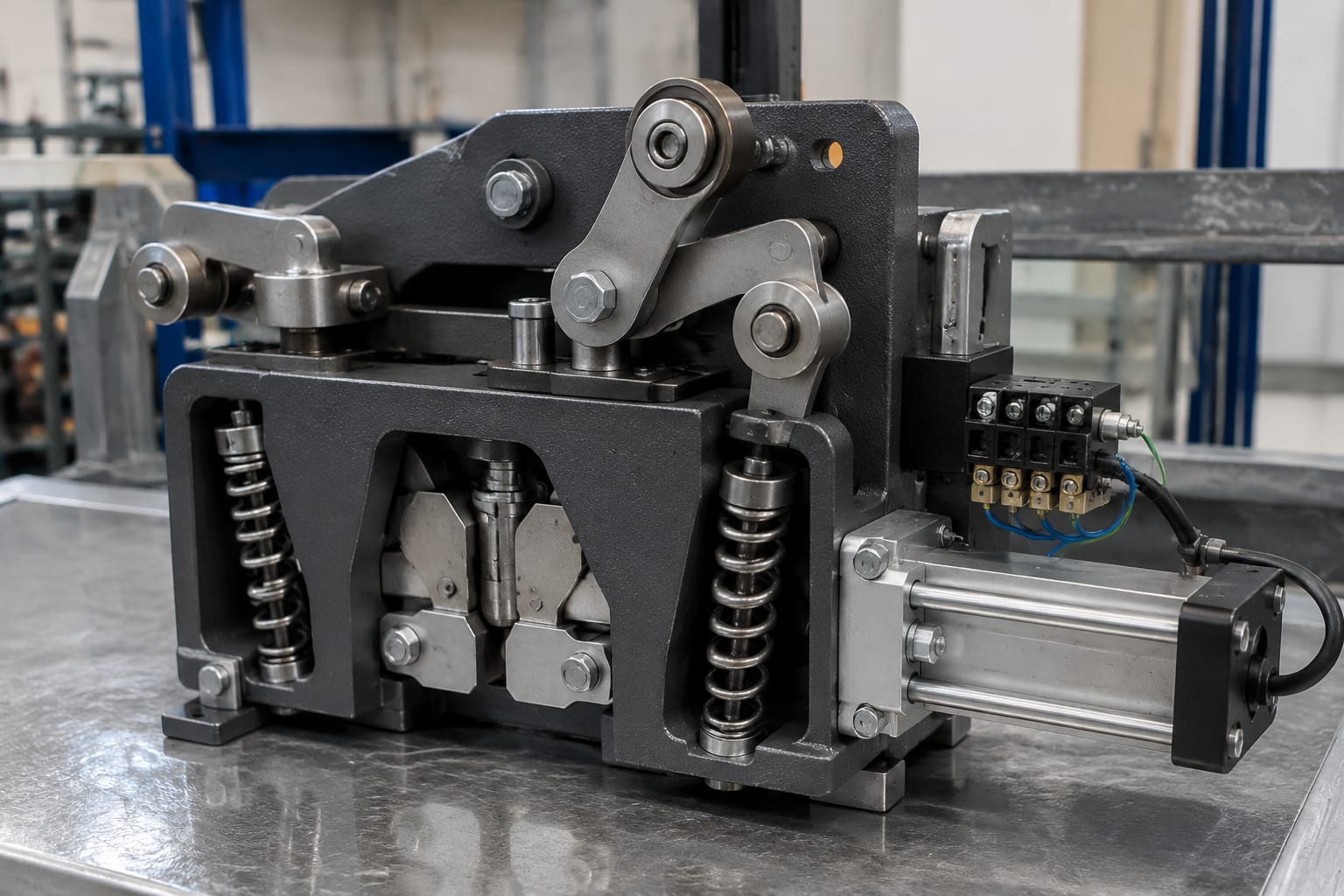
The overspeed governor is the initiating device in a conventional mechanical safety system. It is usually located in the machine room, machinery space, or hoistway, depending on the elevator design. A governor rope runs from the governor down the hoistway, around a tension sheave, and back to the car safety linkage.
The system works as a chain of connected components:
- Overspeed governor: Detects excessive rope speed and grips or trips at its set point.
- Governor rope: Transfers the governor action to the car-mounted mechanism.
- Tension sheave and tension device: Maintain appropriate rope tension and may provide a safety switch to monitor abnormal rope conditions.
- Car safety linkage: Converts rope movement into a mechanical force that operates both safety gear assemblies.
- Safety gear: Grips the guide rails and stops or holds the car.
- Electrical safety circuit: Removes driving power or prevents continued operation as required by the elevator’s safety design.
The linkage must operate both sides of the car frame in a coordinated manner. Binding, unequal travel, missing retaining hardware, corrosion, distorted levers, or excessive play can produce uneven engagement. That can damage rails, create an unreliable stop, or cause one side to engage before the other.
Electrical components are part of the overall safety architecture, but they do not replace the mechanical safety gear. For example, a properly selected elevator brake micro-movement detection switch can support monitoring functions in applicable equipment, while the governor and safety gear remain the mechanical emergency stopping path. Any electrical replacement must be verified against the controller documentation and the specific circuit function.
Progressive versus instantaneous types
The two broad categories most buyers and maintenance teams encounter are progressive and instantaneous safety gear. The correct choice is determined by the original elevator design, rated speed, code requirements, and compatible guide rail system. It is not an upgrade decision based solely on perceived stopping force.
| Feature | Progressive safety gear | Instantaneous safety gear |
|---|---|---|
| Stopping method | Builds braking force over a controlled travel distance | Grips the rails abruptly with minimal stopping travel |
| Typical mechanism | Wedges, rollers, or friction elements that increase rail pressure | Direct gripping jaws or wedges |
| Ride and structural effect | Intended to limit deceleration through progressive application | Produces a more abrupt deceleration |
| Common application context | Generally associated with higher-speed passenger applications and designs needing controlled deceleration | More commonly found in lower-speed applications where permitted |
| Replacement priority | Match rail, speed range, operating direction, linkage geometry, and certified design data | Match rail, speed range, operating direction, linkage geometry, and certified design data |
Progressive safety gear
Progressive safety gear develops braking force as the car moves after activation. Its wedges or gripping members are shaped and loaded to progressively increase pressure against the guide rails. This controlled action is intended to avoid the extreme deceleration associated with an abrupt rail clamp.
Progressive assemblies are sensitive to compatibility. Rail face condition, rail size, lubrication practices where applicable, car frame rigidity, spring condition, wedge geometry, and linkage adjustment all affect performance. A replacement that has the wrong rail interface or actuation travel may not develop its intended braking behavior.
Do not assume a progressive gear can be interchanged solely because it fits a similarly sized rail. Obtain the original manufacturer’s identification, rated parameters, and drawings or product documentation before sourcing.
Instantaneous safety gear
Instantaneous safety gear is designed to grip the rail quickly when actuated. It may use wedge or jaw arrangements that lock against the rail with very little stopping distance. Because the stop is abrupt, permitted use is tied to the elevator’s rated speed and the requirements applicable to the installation.
The term “instantaneous” does not mean unregulated or maintenance-free. These assemblies still require correct clearance, linkage travel, rail compatibility, condition checks, and prescribed testing. Worn gripping surfaces, altered springs, unauthorized machining, or improvised shims can materially change operation.
Some safety gear designs include features intended to limit or control engagement characteristics. Do not classify an assembly by appearance alone. Use the manufacturer identification and technical documentation.
Car and counterweight applications
Car safety gear is the most familiar configuration. It is mounted on the car frame and operates on the car guide rails. In a traction elevator, it is normally triggered by the governor system when overspeed or a specified safety condition occurs.
Counterweight safety gear is a separate application. It is installed on the counterweight frame and operates on the counterweight guide rails when required by the elevator design and applicable code. A counterweight safety system may have a different actuation arrangement and is not automatically interchangeable with car safety gear.
When evaluating either application, confirm:
- Whether the assembly is for the car or counterweight.
- The operating direction: downward-only or bidirectional, as applicable.
- Rated elevator speed and the system’s specified tripping parameters.
- Guide rail type, face dimensions, and rail weight or designation.
- Car or counterweight frame geometry and mounting-hole pattern.
- Governor rope diameter, linkage arrangement, and required operating stroke.
- Whether the original safety gear is part of a listed or certified system.
- Applicable edition of ASME A17.1/CSA B44 and requirements enforced by the local authority having jurisdiction.
A common mistake is treating a counterweight component as a mirrored car component, or assuming left- and right-hand assemblies can be swapped. Markings, mounting orientation, and linkage connections must be verified before ordering.
Common inspection findings
Inspection should address the full operating path, not just the visible gripping faces. The following findings commonly require further evaluation by a qualified elevator mechanic or inspector.
Contamination or rail damage
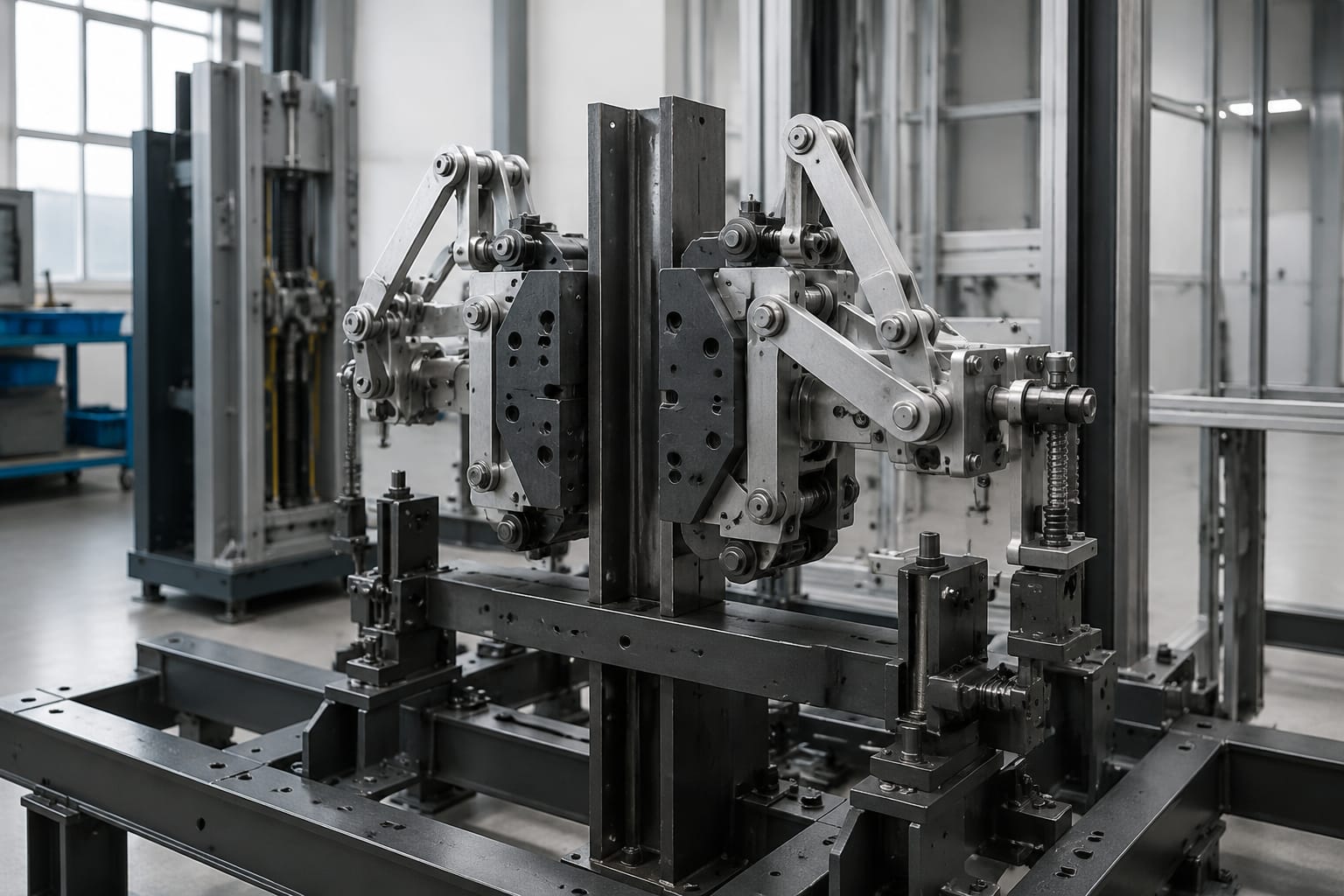
Oil, heavy rust, paint, abrasive residue, and accumulated debris on the guide rail can affect safety gear engagement. Deep scoring, raised metal, damaged rail joints, and rail misalignment can also interfere with predictable operation.
Do not polish, grind, or lubricate a rail simply to make a safety gear “feel smoother” without following the applicable maintenance procedure and manufacturer guidance. Surface treatment that seems helpful during manual movement may impair the assembly’s emergency performance.
Corroded, worn, or altered components
Corrosion around springs, pivots, wedges, jaws, and mounting hardware may reduce movement or compromise material condition. Check for:
- Cracked castings or distorted side plates.
- Broken, weakened, or non-original springs.
- Worn pins, elongated holes, and loose clevis connections.
- Missing cotter pins, clips, or locking devices.
- Weld repairs, ground surfaces, or field modifications not supported by the manufacturer.
- Evidence that gripping elements have contacted the rail unexpectedly.
Any unauthorized modification is a major compatibility concern. Safety gear components are engineered as an assembly; replacing an individual element with an unverified substitute can alter load paths and operating force.
Linkage and governor-rope problems
A governor rope that is excessively worn, improperly tensioned, damaged, or contaminated may not transfer motion reliably. The tension sheave should travel freely within its intended range, and the linkage must not bind across normal car travel.
Check that the governor trip mechanism, rope, tension device, and car linkage are maintained as a coordinated system. A safety gear inspection that excludes the governor and rope path is incomplete.
Electrical safety circuit concerns
Safety-related electrical contacts, switches, brackets, and wiring need the same disciplined identification as mechanical parts. A damaged mounting arrangement can create intermittent contacts or incorrect switch actuation. Where the installation uses this type of component, verify the physical configuration and circuit rating before selecting a brake lock micro switch bracket.
Do not bypass safety switches to diagnose a fault or return an elevator to service. Temporary bypasses can defeat protective functions and may violate site procedures and code obligations.
Identification data for replacement
A clear data package reduces incorrect orders and avoids delays caused by physically similar but incompatible safety gear. Start with the original identification plate or stamped markings, then document the installed assembly before removal.
Useful replacement information includes:
| Information to collect | Why it matters |
|---|---|
| Manufacturer, part number, and serial or production marking | Establishes the original design and possible approved replacement path |
| Safety gear type and model | Distinguishes mechanical design, operating characteristics, and component family |
| Elevator rated speed | Helps confirm suitability of the safety gear and governor relationship |
| Car or counterweight application | Prevents ordering an assembly intended for the wrong frame |
| Guide rail designation and measured rail face dimensions | Determines rail compatibility |
| Left-hand, right-hand, or paired assembly orientation | Ensures correct mounting and linkage connection |
| Mounting dimensions and clear photographs | Confirms frame interface and avoids orientation errors |
| Governor rope diameter and linkage details | Confirms required actuation arrangement and travel |
| Existing documentation and local inspection requirements | Supports code review, testing, and records |
Take photos from several angles before disassembly. Include the identification plate, mounting interface, linkage connection, guide rail contact area, and a wider photo showing the assembly’s location on the frame. Measurements should be taken with appropriate tools and recorded in consistent units.
Do not rely on a photo alone. The same exterior profile may be used across different rail sizes, force ranges, or mounting variants. Similarly, a used assembly with an unreadable plate should be treated as an identification problem, not as a generic replacement template.
For multi-brand sourcing, Kelevator supplies elevator spare parts to B2B importers, distributors, maintenance contractors, modernization companies, and OEM buyers. A sourcing request is more likely to be actionable when it includes the identification data above along with the quantity, condition of the existing component, and any required documentation.
Why adjustment and testing require specialists
Safety gear adjustment and testing involve a high-consequence mechanical system. The process can expose personnel to moving equipment, suspended loads, electrical hazards, and an unintended safety application. It also requires an understanding of the installation’s design, the governing code, and the test procedure appropriate to that equipment.
Qualified elevator personnel should determine:
- Whether the governor trip speed and safety gear settings are correct for the rated car speed.
- Whether the linkage actuates both safety gears evenly and with required travel.
- Whether the guide rails, rail brackets, fishplates, and car frame can support the expected loads.
- Whether a test is required after adjustment, component replacement, repair, or safety activation.
- Which protective measures, access controls, and rescue procedures are required during testing.
- What must be witnessed or accepted by the authority having jurisdiction.
An incorrect adjustment can be dangerous in both directions. A system that trips too easily may create an unnecessary emergency stop and rail damage. A system that does not trip or engage at the required condition can fail to provide the intended protection.
Mechanical and electrical work should also be coordinated. For controller-side safety circuitry, confirm the exact board, relay configuration, terminals, and revision rather than ordering by a broad description. For example, a Toshiba elevator safety circuit relay board should be matched to the applicable controller documentation and installed by personnel qualified to verify the safety circuit after work is complete.
Documentation after safety work
Good records make later inspections, troubleshooting, and procurement substantially easier. After safety gear inspection, adjustment, activation, repair, or replacement, maintain documentation that identifies the work performed and the equipment affected.
The record should normally include:
- Elevator location or equipment identifier.
- Date, responsible company, and qualified personnel involved.
- Safety gear manufacturer, model, part number, and orientation.
- Governor and governor-rope identification where relevant.
- Guide rail identification and observations about rail condition.
- Condition findings, replaced parts, and any corrective work.
- Adjustment values or settings recorded according to the applicable procedure.
- Test method, results, exceptions, and return-to-service authorization.
- Required inspection or authority documentation under local rules.
Keep original component tags, purchase records, photos, and test records with the maintenance file. This is particularly useful during modernization, when an older installation may have incomplete drawings or several generations of replacement parts.
FAQ
Is lift safety gear the same as an elevator brake?
No. The machine brake is used for normal stopping and holding at landings. Lift safety gear is an emergency mechanical device that grips the guide rails after actuation by the governor and linkage system.
Can safety gear be reset after it trips?
It may be mechanically reset only after qualified personnel inspect the cause of activation and the affected equipment. Resetting without determining why the system operated can leave the elevator unsafe or conceal damaged rails, linkage, governor components, or car-frame parts.
Can a safety gear be replaced with a similar-looking model?
No. Visual similarity is not sufficient. Confirm the original manufacturer and model, rated speed, rail type, application, mounting geometry, operating direction, linkage requirements, and applicable approval or code requirements.
How often should elevator safety gear be tested?
The required interval and method depend on the elevator type, governing code edition, local authority requirements, manufacturer instructions, and maintenance program. Follow the requirements applicable to the installation rather than using a generic interval.
For a replacement inquiry or internal sourcing review, assemble the identification plate details, rail dimensions, rated speed, orientation, mounting photos, and maintenance records first. That information provides the basis for a technically defensible compatibility review.