
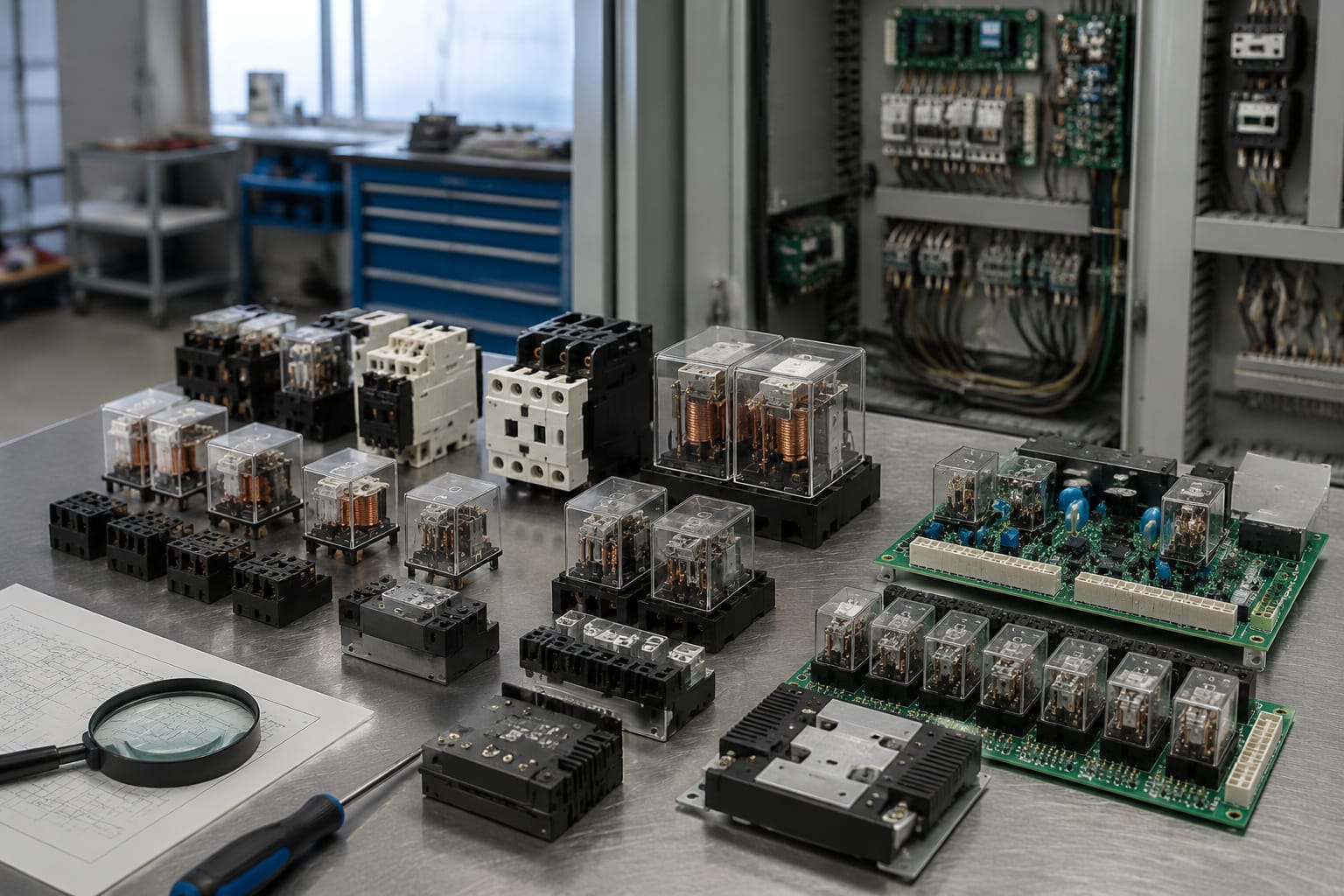
An elevator relay is a control device that opens, closes, or transfers an electrical circuit in response to a control signal. In elevator equipment, relays may command door motion, operating modes, indicators, interlocks, safety-chain logic, and interfaces between a controller and external devices. The correct replacement is not simply a relay that fits the socket: its coil voltage, contact arrangement, load rating, timing behavior, suppression, and board revision must all match the circuit’s requirements.
When a relay appears faulty, diagnose the surrounding circuit before replacing it. A burned contact may be the result of an overloaded load, a failing coil may reflect incorrect control voltage, and an unenergized relay may be responding correctly to an open safety circuit. Only qualified elevator personnel should test or replace components in energized controller, door, or safety-related circuits.
What elevator relays control
An elevator relay allows a low-power command circuit to switch or isolate another circuit. In older relay-based controllers, relays perform much of the system logic directly. In newer microprocessor controllers, they commonly serve as output interfaces, safety interfaces, or isolation devices between electronic boards and field equipment.
Depending on the design, an elevator relay can control or supervise:
- Door open, close, nudging, and door-zone functions
- Car and hoistway door interlock circuits
- Direction, leveling, and travel command interfaces
- Car calls, hall calls, lanterns, gongs, and position indicators
- Brake, motor-control, and contactor interface circuits
- Fire service, emergency power, inspection, and independent-service inputs
- Car-top, pit, hoistway, and machine-room signals
- Safety-chain status and permissive logic
- Communication or interface signals between controller boards and accessories
A relay often does not power a major load directly. For example, its contacts may provide a permissive signal to another board or energize a contactor coil that then controls a higher-current load. That distinction matters during troubleshooting. A relay with contacts rated for a few amps may be appropriate for a control coil but unsuitable for switching a motor, heater, or other power load.
The circuit diagram, controller documentation, board markings, and terminal labels establish the relay’s actual job. Never assume its function based solely on location or a handwritten cabinet label.
Electromechanical and solid-state relays
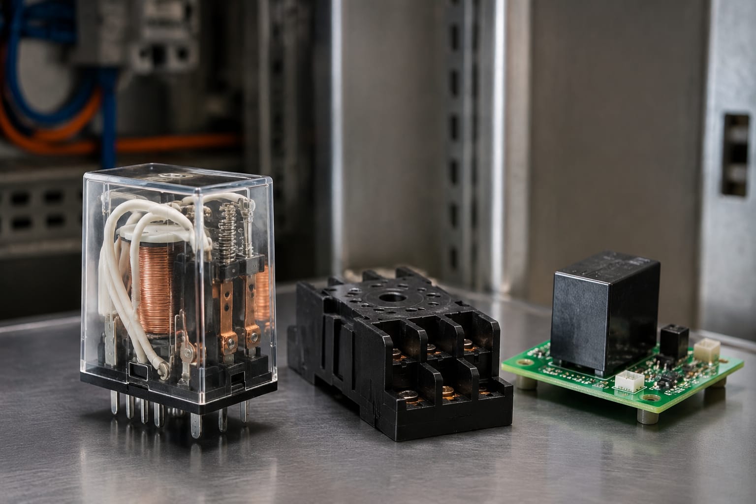
The two broad elevator relay categories are electromechanical relays and solid-state relays. Both switch circuits, but their operating behavior and failure patterns differ.
| Characteristic | Electromechanical relay | Solid-state relay |
|---|---|---|
| Switching method | Moving armature and metal contacts | Semiconductor switching device |
| Audible operation | Usually clicks when energized | Silent |
| Typical output | AC or DC, depending on contact and relay design | Usually specified for a particular AC or DC application |
| Isolation | Mechanical contact separation when open | Electronic isolation; may have off-state leakage |
| Wear mechanism | Contact erosion, pitting, contamination, mechanical fatigue | Heat stress, semiconductor failure, surge damage |
| Common failure state | Coil open, weak operation, welded or high-resistance contacts | Open output, shorted output, overheating |
| Diagnostic consideration | Inspectable and testable contacts and coil | Requires attention to leakage, voltage drop, heat, and load type |
Electromechanical relays
An electromechanical elevator relay uses a coil to pull an armature, changing the position of one or more contacts. Its contact forms may be normally open (NO), normally closed (NC), or changeover/form C. Multi-pole versions switch several isolated circuits at once.
These relays are common where visible contact state, galvanic isolation, or switching flexibility is useful. They may be plug-in devices with replaceable relay modules or soldered components mounted on a relay board.
Typical problems include:
- Open or shorted coil windings
- Pitted, oxidized, contaminated, or welded contacts
- Weak spring tension or armature binding
- Socket heat damage or loose terminal retention
- Contact transfer that changes the circuit’s intended state
A relay can click and still be defective. The coil may energize normally while worn contacts create excessive resistance, intermittent operation, or a failure to carry load.
Solid-state relays
A solid-state relay (SSR) uses semiconductor components rather than moving contacts. It can offer fast, quiet switching and long switching life when correctly applied. It also introduces characteristics that can surprise technicians accustomed to mechanical contacts.
An SSR may have an on-state voltage drop and generate heat under load. It may pass a small leakage current when “off,” which can affect sensitive inputs, LEDs, electronic boards, or circuits without a suitable bleed path. Some AC SSRs switch at a zero crossing, which can be beneficial for certain resistive loads but may not suit every control requirement.
Do not replace an electromechanical relay with an SSR, or an SSR with a mechanical relay, merely because the nominal voltage and current appear similar. Confirm the original switching technology, control input, load type, isolation requirement, fail state, mounting, heat dissipation requirements, and circuit behavior.
Relay boards in door and safety circuits
Many elevators use relay boards rather than individual relays wired point to point. A relay board may combine relays with fuses, diodes, optocouplers, resistors, terminal connectors, status LEDs, and printed circuit traces. The board may be an interface between a controller and door equipment, car-top devices, safety circuits, or auxiliary accessories.
Door-related relay boards can handle signals such as door-open commands, door-close commands, door lock monitoring, door-zone status, bypass functions, or inputs from door operators. A board associated with a door bypass circuit deserves particular caution because its intended function, wiring, and operating conditions are safety-sensitive. Verify the specific controller and application before considering a door bypass control relay board.
Car-top relay boards may distribute or interface signals for inspection controls, car-top devices, door equipment, and traveling-cable circuits. The board’s connector layout and part number are as important as the relays fitted to it. For applications that call for this type of assembly, compare the physical and documented details of an elevator car-top relay board.
Safety and door circuits require special discipline:
- Do not jumper a relay contact to force a permissive condition.
- Do not bypass an interlock, gate switch, stop switch, or safety input for normal operation.
- Do not assume an illuminated board LED proves the output contact is good.
- Treat a relay board as an assembly unless a documented repair procedure permits component-level work.
- Record original terminal positions and connector orientation before removal.
In many cases, a board-level replacement is more reliable than replacing one relay on a board with unknown trace damage, damaged solder joints, or failed support components. However, a board replacement must be an exact compatibility decision, not a visual match.
Common signs of relay failure
Relay failure can present as a complete outage, an intermittent fault, or an issue that appears only under load. The symptom helps narrow the test path, but it does not identify the defective part by itself.
Common signs include:
- A relay does not pull in when its command condition is present.
- The relay chatters, buzzes, or repeatedly drops out.
- A relay clicks but the commanded device does not operate.
- The controlled function works intermittently, especially after vibration or temperature changes.
- Contacts remain closed after the coil is de-energized.
- A function remains active when it should be off.
- Relay housing, socket, terminals, or board traces show heat discoloration.
- The coil has an unusual odor, visible damage, or measurable open circuit.
- A fuse opens repeatedly when the relay command is issued.
- Door operation, car-top functions, or controller inputs fail only in one mode.
Chatter deserves close attention. It can result from a failing relay coil, but it is often caused by low or unstable coil voltage, poor neutral or common connections, a loose connector, a defective power supply, excessive voltage drop, or a command signal that is cycling. Replacing the relay without finding the voltage problem can lead to another failure.
Similarly, welded contacts may indicate that the relay was asked to interrupt more current than intended, switched an inductive load without proper suppression, or experienced a downstream short. Examine the load circuit before installing a replacement.
Check coil voltage and contact ratings
A relay replacement must match the original electrical and functional requirements. The manufacturer part number is the best starting point, but the relay label, board documentation, wiring diagram, and measured circuit conditions should all agree.
Coil specifications to verify
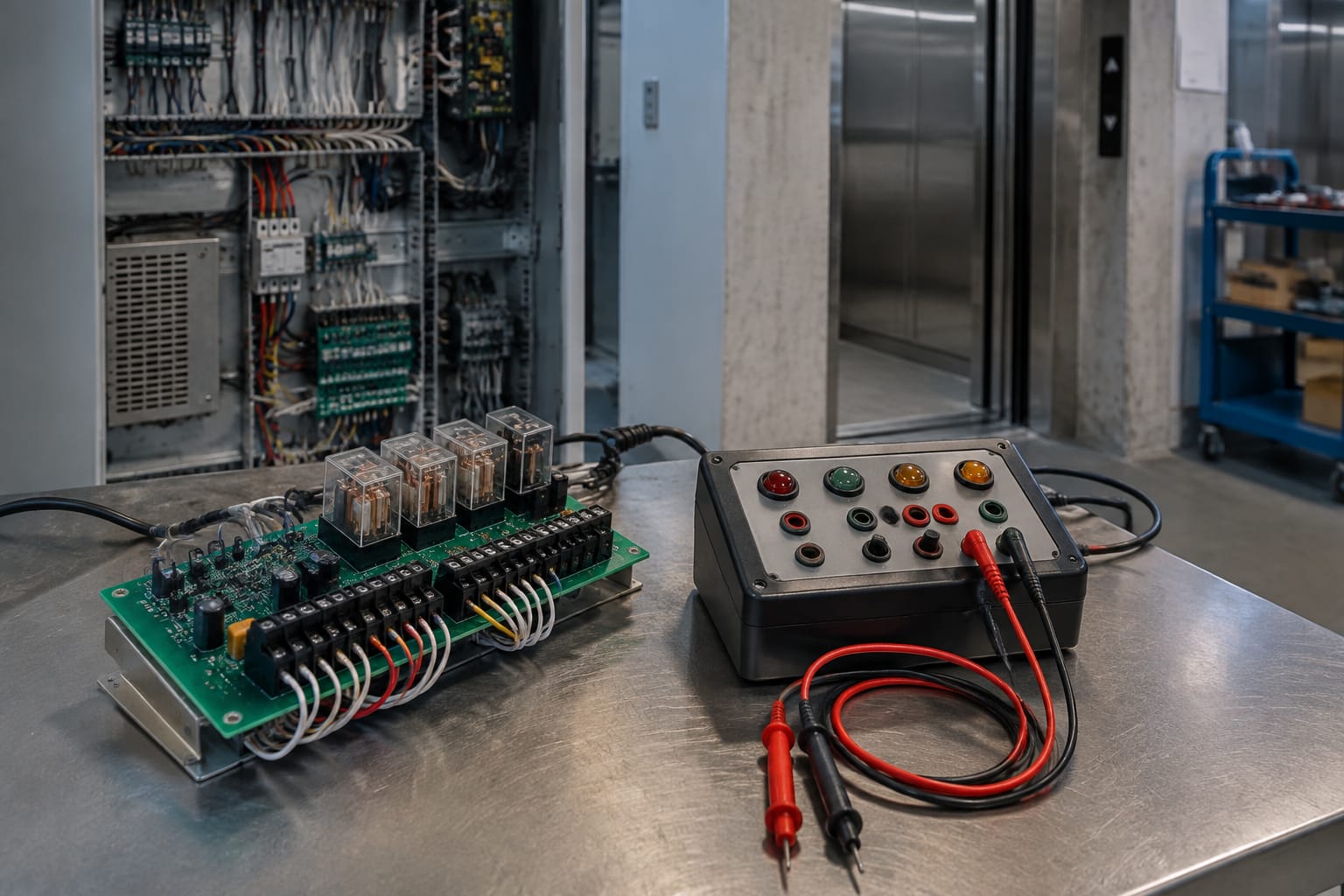
The coil is the control side of an electromechanical relay. Confirm:
- Rated coil voltage: Common control voltages include 24 VDC, 24 VAC, 48 VDC, 110/120 VAC, and other values depending on the equipment. AC and DC coils are not interchangeable.
- Coil type: Verify AC versus DC, polarity where applicable, and any integral diode, resistor, or LED.
- Operating range: A relay may require a minimum pickup voltage and have a different drop-out voltage. Nominal voltage alone does not show whether the circuit is delivering adequate power.
- Coil current or resistance: Compare against documentation when diagnosing an open, shorted, or incorrect coil.
- Duty cycle: Some relays are designed for continuous energization; others are not.
Measure coil voltage at the relay terminals while the circuit is commanded to energize. A measurement taken only at the power supply can miss voltage drop across wiring, connectors, switches, board traces, or other series devices.
Contact specifications to verify
Contacts are the load side. Confirm:
- Contact form: SPST-NO, SPST-NC, SPDT/form C, DPDT, or another arrangement
- Number of poles: A replacement must provide every required isolated contact set.
- Current rating: Check the rating for the actual load type, not only a general maximum value.
- Voltage and current type: AC and DC switching ratings can differ substantially.
- Load category: Resistive, inductive, lamp, motor, contactor coil, and electronic loads impose different switching demands.
- Minimum load considerations: Low-level signal contacts may need suitable contact materials for reliable switching.
- Switching versus carry rating: A relay may carry a current continuously that it cannot safely make or break at the same rating.
For inductive loads such as coils, contactors, solenoids, and some door equipment, verify whether the original design uses a flyback diode, RC snubber, varistor, or another suppression method. Adding, removing, or changing suppression without understanding the circuit can alter release time, introduce polarity problems, or damage electronic outputs.
Diagnose the circuit before replacement
A structured diagnosis prevents an unnecessary relay replacement and helps identify why the relay failed. Use the controller schematic and the equipment manufacturer’s test procedure whenever available.
A practical sequence is:
- Make the equipment safe. Follow site lockout/tagout requirements and elevator-specific procedures. Determine whether the circuit is part of a safety function and whether testing must be performed in a controlled maintenance mode.
- Identify the relay and its circuit role. Record the part number, board number, terminal labels, relay designation, connector positions, and controller model.
- Check the command condition. Confirm whether the controller or input device is actually requesting the relay to operate.
- Measure the coil at the relay. With the proper command present, test for correct voltage and polarity at the coil terminals.
- Check coil continuity with power removed. Compare measured resistance to known-good documentation or an identical verified relay when appropriate.
- Test the contacts with the circuit de-energized. Verify expected open and closed states. A continuity test alone may not reveal high resistance under load.
- Verify output behavior under the correct test conditions. Measure voltage drop or load-side operation safely, according to the circuit design.
- Inspect related components. Check sockets, terminals, board solder joints, fuses, wiring, suppression components, connectors, and the downstream load.
- Find the underlying cause. Resolve overload, short circuit, loose connection, moisture contamination, vibration, or incorrect control voltage before fitting a new relay.
Do not rely on swapping relays between positions as a first diagnostic method. Relays that look alike can have different coil voltages, contact forms, internal suppression, timing, or circuit assignments. An incorrect swap can create a new fault or defeat a designed interlock.
Match boards, connectors, and revisions
A complete relay board must match more than its overall shape. Elevator parts can have similar-looking housings and connectors while using different pin assignments, relay logic, firmware expectations, or component revisions.
Before ordering a relay board, verify:
| Compatibility check | Why it matters |
|---|---|
| Original part number | The most direct identifier for intended replacement |
| Board assembly number and revision | Revisions may change circuitry, connectors, or supported equipment |
| Controller and door operator application | A board may fit physically but be intended for another system |
| Connector count, keying, and pin layout | Prevents incorrect mating and signal misrouting |
| Terminal labels and wire positions | Confirms field connections correspond to the replacement |
| Relay coil and contact configuration | Ensures the board provides the required control and load functions |
| Supply voltage and input/output signal type | Avoids damage to the board or controller |
| Mounting dimensions and grounding arrangement | Ensures safe, correct physical installation |
| Documentation or approved cross-reference | Confirms that any supersession is legitimate |
Photographs are useful for an initial comparison but are not sufficient evidence of compatibility. Read markings on both sides of the board where accessible, including labels near connectors and relay designations. Document the complete assembly rather than only one prominent relay.
For general interface applications, an elevator interface relay board should be evaluated against the original board identifiers, connectors, wiring diagram, and required inputs and outputs. A compatible replacement must preserve the system’s intended logic and electrical boundaries.
For B2B sourcing, provide the supplier with clear photos, full part and revision numbers, equipment application details, connector information, and the quantity needed. Kelevator supplies multi-brand elevator spare parts to B2B importers, distributors, maintenance contractors, modernization companies, and OEM buyers. Those details help a sourcing team evaluate whether a requested relay or board is the correct item rather than a superficial substitute.
Test the system after replacement
Replacement is complete only after the circuit and elevator function have been tested according to the applicable maintenance procedure. A relay that energizes is not necessarily proof that the controlled function, safety logic, and fault monitoring all operate correctly.
After installation:
- Verify the board and relay are fully seated, secured, and connected in the original orientation.
- Confirm terminal screws, plug connectors, retaining clips, and grounding points are correctly installed.
- Restore power using the proper procedure and inspect for unexpected heat, odor, noise, or fault indications.
- Check coil voltage and commanded relay operation.
- Verify the controlled function operates in the required modes.
- Confirm the function releases or resets correctly when its command is removed.
- Test relevant door, inspection, fire service, emergency power, or safety-related behavior only under the approved procedure for that equipment.
- Check for recurring faults after the system has cycled under normal conditions.
- Update the maintenance record with the part number, revision, fault symptoms, test results, and any underlying repair made.
Avoid repeated rapid cycling during testing unless the equipment procedure specifically calls for it. Frequent cycling can heat coils, stress contacts, and obscure the original fault. If the replacement relay or board becomes hot, chatters, or causes a fuse to open, remove the equipment from service as appropriate and return to circuit diagnosis.
The practical rule is simple: match the relay’s electrical function and the board’s documented compatibility, then prove the circuit works safely after installation. For a replacement decision, start with the original part and revision data, confirm coil and contact requirements, and retain the wiring and fault information with the order.
Related product references
For practical catalog examples related to this topic, review Door Bypass Control Relay Board OTIS elevator parts lift accessories, Elevator car top relay board KCE KONE lift parts, and interface board relay board lift parts elevator accessories. Confirm the exact model, dimensions, ratings, and connectors before ordering.