
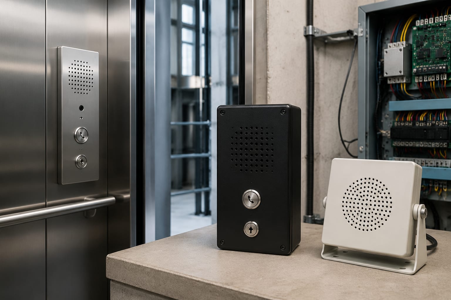
Elevator intercom systems provide the protected, two-way voice path used to communicate with passengers in an elevator car, typically during an entrapment, equipment fault, or service event. A dependable system is more than a handset or speaker: it includes the car station, the receiving station or monitoring point, power, wiring, and a method for identifying which elevator is calling.
For maintenance and modernization work, the right replacement depends on the existing architecture. Confirm whether the system is a simple car-to-machine-room circuit, a multi-car installation with a duty-room station, or a monitored emergency communication system before selecting parts. Similar-looking stations can differ in power requirements, connector pinouts, signaling, audio method, and compatibility with the controller.
What an elevator intercom system does
An elevator intercom system allows people in the car to speak with an authorized person outside the car. The calling device may be a built-in speakerphone, a push-to-talk unit, a handset, or a dedicated emergency communication panel. The receiving side may be in the machine room, a building security office, a superintendent’s office, a central monitoring station, or another approved location.
In practical terms, the system should enable the receiving party to:
- Recognize that an elevator is calling.
- Identify the originating car or location.
- Establish intelligible two-way communication.
- Speak to passengers without requiring them to exit the car.
- Maintain operation through the power conditions required by the installation and applicable code.
An intercom is not necessarily the same as an elevator emergency telephone. Some elevators use a dedicated telephone line or cellular communicator for emergency calls; others use an intercom arrangement within the building; some installations combine both functions. The distinction matters because a component designed for an internal intercom circuit may not substitute for a code-required emergency telephone or remote monitoring device.
Before changing equipment, determine the system’s intended role and review the requirements enforced by the authority having jurisdiction. In the United States, applicable requirements can depend on the adopted edition of ASME A17.1/CSA B44, local code amendments, the building’s emergency communications plan, and the elevator’s age or modernization scope.
Two-way and multi-station configurations
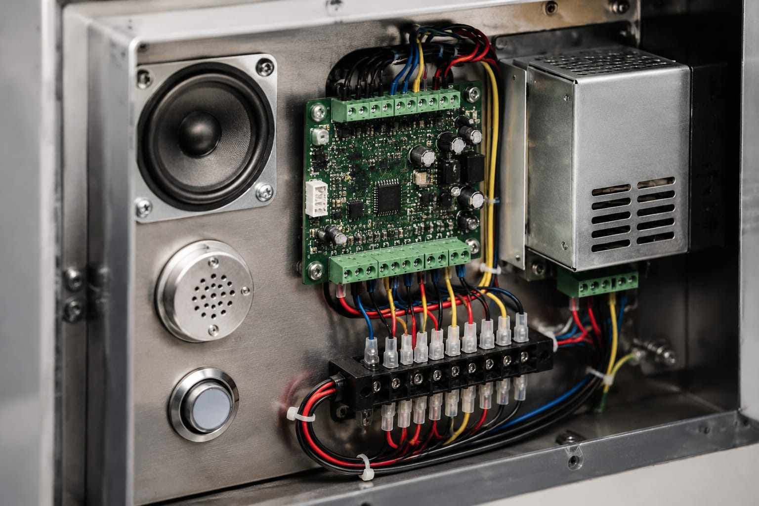
The configuration determines how many locations can call, receive calls, and communicate at the same time. It also affects the wiring count, station address or identification method, and power-supply design.
| Configuration | Typical use | How communication works | Key replacement concern |
|---|---|---|---|
| Point-to-point two-way | One car and one receiving location | Car station communicates directly with a machine-room or duty-room station | Match the audio circuit, call signaling, and supply voltage |
| Car-to-machine-room with extension | A car plus one or more authorized extension locations | The primary station may pass or share calls with extensions | Confirm whether extensions are parallel, switched, or system-specific |
| Multi-car, single receiving station | Several elevators served by one duty room or security desk | Receiving station identifies and answers a selected car | Verify car identification, station capacity, and selector compatibility |
| Multi-station intercom network | Larger buildings, groups, or service facilities | Multiple car, machine-room, lobby, and duty-room points share a controlled system | Do not assume stations are interchangeable across the network |
| Intercom with remote emergency communications | Sites using remote monitoring or a dedicated emergency line | Intercom may be local while emergency calls route externally | Keep the local intercom and emergency-call functions clearly separated |
A point-to-point system is generally the simplest to diagnose because the signal path is direct. However, even a basic installation can fail if a replacement station uses a different impedance, polarity convention, relay interface, or power requirement.
Multi-station systems require more discipline. A new car station may physically fit the panel opening but still fail to identify the car correctly, occupy the audio channel incorrectly, or prevent other stations from calling. In these installations, document the existing station model, terminal labeling, controller interface, and system diagram before removing equipment.
Full-duplex, half-duplex, and push-to-talk operation
Intercom systems may permit both parties to speak simultaneously, allow one direction at a time, or require a push-to-talk action. These operating styles are not automatically interchangeable.
- Full-duplex systems feel more like a telephone conversation but depend on echo control and compatible audio design.
- Half-duplex systems alternate the active audio direction, often through switching circuitry.
- Push-to-talk systems require deliberate operation and can be easier to understand in noisy equipment spaces, but depend on the switch and associated contacts working correctly.
When upgrading, preserve the operating behavior unless the entire system is being redesigned. Installing a full-duplex station on a circuit intended for push-to-talk operation can produce weak audio, feedback, or no communication at all.
Car, machine-room, and duty-room stations
Each station serves a different role and should be selected according to its location, environment, and interface.
Car stations
A car station is the passenger-facing endpoint. It may contain a microphone, speaker, call button, status indicator, handset, or a combination of these components. It must withstand vibration, cleaning practices, passenger use, and the acoustic conditions of the car.
For a car-station replacement, check:
- Faceplate dimensions, mounting points, and panel cutout.
- Speaker and microphone arrangement.
- Call-button type, indicator behavior, and contact configuration.
- Harness connector, terminal block, wire colors, and pinout.
- Audio circuit type and nominal operating voltage.
- Whether the station is part of an intercom system, emergency telephone system, or both.
- Accessibility and code implications for the altered fixture.
Do not select a car station solely by brand family or visual similarity. Elevator manufacturers and aftermarket systems can use different internal wiring even when faceplate layouts appear nearly identical.
Machine-room stations
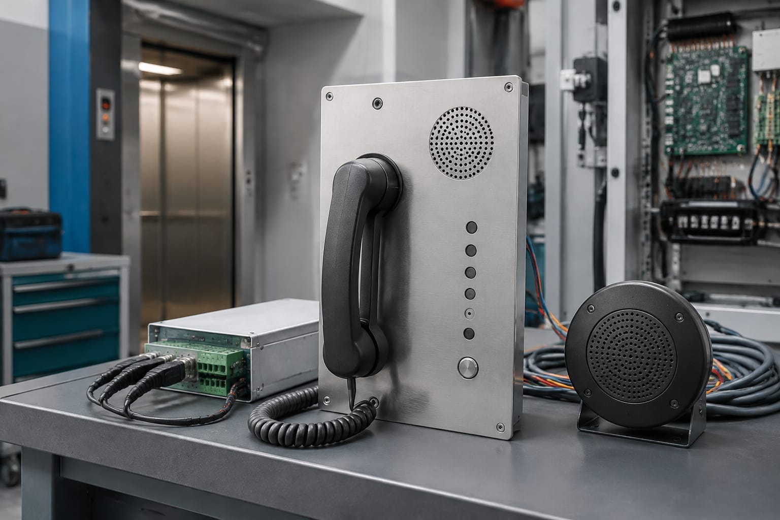
A machine-room station gives technicians or designated building personnel a local communication point. It may be a wall-mounted unit, handset, speaker station, or component integrated into the controller-area layout.
Machine-room locations introduce specific risks: electrical noise, heat, dust, vibration, and nearby machinery can affect communication quality. Route low-voltage communication wiring away from power conductors where required and practical, and follow the system documentation for shielding and grounding. A clear call indicator is also important because a ringing or visual alert can be missed in a noisy room.
Duty-room and security-desk stations
Duty-room stations are common where building staff, security personnel, or a monitoring desk receive calls from multiple cars. These stations may include car selection buttons, illuminated identifiers, annunciators, handsets, or displays.
For a multi-car duty-room station, verify the maximum number of served locations and how the system identifies a call. Identification may rely on separate wires, relay contacts, assigned terminals, address settings, or controller logic. Replacing only the central station without understanding that method can leave the operator unable to determine which car initiated the call.
When sourcing multi-brand components, provide the station’s part number and clear photos of front and rear labels, connectors, and terminals. Kelevator supplies multi-brand elevator spare parts for B2B buyers, but compatibility should still be confirmed against the actual system rather than assumed from the elevator brand.
Power supplies and backup power
Intercom equipment may operate from a dedicated low-voltage supply, a controller-provided circuit, a communications cabinet, or an integrated power module. The supply must meet the system’s voltage type, capacity, polarity, regulation, and backup requirements.
A dedicated supply can serve more than one station, so replacing it without a load assessment can create system-wide issues. Confirm:
- Input power requirements and protective device arrangement.
- Output voltage type: AC or DC.
- Rated output capacity and expected connected load.
- Polarity and terminal assignments.
- Whether the supply includes charging, supervision, alarm contacts, or distribution functions.
- Battery type, condition, and replacement requirements where backup power is provided.
- Required operation during loss of normal building power.
A power supply that reads correctly with no load may still collapse under a call condition because of a weak transformer, failing capacitor, degraded battery, corroded connection, or overload. Measure at the supply and again at the station while the system is operating.
For installations using a dedicated manufacturer-style supply, compare the input and output markings, connector arrangement, mounting, and system role before ordering. A dedicated elevator intercom power supply should be evaluated as part of the complete communication circuit, not as an isolated electrical part.
Backup power needs are installation-specific. Do not assume that any battery-backed intercom supply meets the emergency communication requirements applicable to a particular elevator. Confirm the complete emergency communications path, including the car equipment, communications link, receiving endpoint, and any external service or building infrastructure.
Wiring and communication interfaces
Elevator intercom wiring can be simple or highly system-specific. Older systems may use separate conductors for speaker audio, microphone audio, common, call signal, and power. Newer systems may use a shared bus, digital interface, controller input/output modules, or a dedicated communication cable.
Start with the diagram, terminal designations, and field verification. Wire colors are useful clues but are not proof of function, especially after prior repairs.
Common interface types
| Interface | Typical characteristics | What to verify before replacement |
|---|---|---|
| Separate analog audio conductors | Individual speaker, microphone, common, and call wires | Signal allocation, common reference, impedance, polarity where applicable |
| Powered analog station | Audio pairs plus low-voltage supply | AC/DC type, voltage range, current draw, polarity, and call circuit |
| Relay or dry-contact call signal | A station triggers an external annunciator or controller input | Normally open/closed state, contact rating, supervision, and shared common |
| Shared multi-station bus | Stations connect to common communication conductors | Bus topology, addressing, termination, permitted station types |
| Controller-integrated communication interface | Audio and call functions pass through elevator control equipment | Controller version, interface board, firmware dependencies, and approved wiring |
Avoid using wire-count matching as the only compatibility test. Two six-conductor systems can assign the conductors differently, and a spare conductor may be used for call identification, lamp control, shielding, or future expansion.
Shielding and grounding deserve attention when audio is noisy. A shield connected incorrectly at multiple points can create unwanted ground paths; a shield left open where the manufacturer expects termination can reduce noise protection. Follow the equipment documentation rather than applying a universal grounding rule.
For a replacement car unit, compare the existing device against the connector style and terminal layout of the proposed elevator intercom phone. Record each termination before disconnecting it, including jumpers and any wires doubled under a terminal.
Audio and call-quality problems
Most intercom faults fall into a few observable patterns. The symptom helps narrow the diagnosis, but testing should occur at both ends of the circuit.
| Symptom | Likely areas to inspect | Practical diagnostic step |
|---|---|---|
| No call indication | Call button, station switch, call wiring, relay/interface, supply | Test the call contact and trace the signal at the receiving station |
| Call indication but no audio either way | Lost power, open common, failed station, disconnected harness | Confirm operating voltage and continuity before replacing audio parts |
| Passenger can hear staff, but staff cannot hear passenger | Car microphone, microphone circuit, connector, station electronics | Test microphone path and inspect car-top/traveling-cable connections |
| Staff can hear passenger, but passenger cannot hear staff | Car speaker, speaker circuit, amplifier/output stage | Check speaker continuity and output signal under a live call |
| Weak, distorted, or intermittent audio | Loose terminals, corrosion, water intrusion, failing supply, damaged cable | Compare voltage and audio behavior at the source and endpoint |
| Feedback or howling | Microphone/speaker placement, gain setting, incompatible station type | Confirm the correct station type and inspect mounting/sealing |
| Noise when elevator moves | Traveling cable conductor, shielding, grounding, induced electrical noise | Flex-test where safe, inspect traveling-cable terminations, isolate noise sources |
Traveling cables are a frequent location for intermittent car communication faults because conductors move with the elevator. A problem that appears only at certain landings, in motion, or after vibration should prompt inspection of the car-top connections and traveling-cable path. Do not perform testing where it creates an unsafe exposure to moving equipment or energized circuits.
Poor call quality can also be caused by the receiving environment. A working machine-room station may be difficult to use near running equipment, while a duty-room station may be affected by poor handset condition, nearby radio equipment, or a damaged cord. Test actual intelligibility in both directions, not just the presence of a tone or relay click.
Replacement and upgrade planning
A successful replacement begins with identifying the function that must be preserved. The goal is not merely to replace a failed-looking station; it is to restore or improve the communication path without creating a mismatch elsewhere in the system.
Document the existing installation
Before ordering or removing parts, collect:
- Elevator manufacturer, controller type, and elevator identifier.
- Intercom system manufacturer and complete part numbers.
- Photos of the station front, rear, labels, terminals, and connectors.
- Wiring diagram, installation manual, or prior service records when available.
- Supply input/output markings and battery information, if applicable.
- Number and type of connected stations.
- The present operating sequence: who calls whom, how a call is indicated, and how calls are answered.
- The specific fault and whether it affects one car or the whole system.
This record helps distinguish a station-level failure from a shared supply, central station, or wiring problem.
Choose between like-for-like replacement and modernization
A like-for-like replacement is usually appropriate when the existing architecture works, the correct part is available, and the fault is limited to a discrete component. It minimizes rewiring and preserves familiar operation.
An upgrade may be justified when components are no longer supportable, communication quality is unreliable, the receiving location no longer matches building operations, or the emergency communication arrangement needs broader review. An upgrade can involve more than the car station: it may require a new supply, central receiver, wiring changes, controller interface, and commissioning.
A modernization project should assess the entire path from the car to the person receiving the call. Replacing a speakerphone while leaving degraded field wiring, an undersized supply, or an obsolete receiving station in place often produces an incomplete result.
Avoid common procurement mistakes
- Ordering by elevator brand alone instead of the intercom system part number.
- Replacing a complete station when the problem is a shared power supply or broken conductor.
- Treating a local intercom as a substitute for a required emergency telephone arrangement.
- Ignoring call identification in a multi-car system.
- Failing to verify AC versus DC supply and polarity.
- Omitting mounting dimensions and connector photos from a sourcing request.
- Assuming a new station will operate on legacy wiring without checking the interface.
- Performing only a bench test instead of testing communication from the installed car.
For car-side replacements, a Hitachi elevator intercom system component may be relevant when the existing system and part identification align. Confirm the exact application, wiring arrangement, and station role before using any replacement component.
Functional and emergency-call testing
Testing should confirm the complete installed function, not simply that a component powers on. Coordinate testing with the building representative, monitoring party, and any required elevator personnel so calls are recognized as test calls and normal service procedures are maintained.
A practical functional test includes:
- Place a call from each car station.
- Confirm the intended machine-room, duty-room, or monitoring location receives the alert.
- Verify the receiving party can identify the calling elevator where multiple cars are served.
- Establish two-way speech and check intelligibility in both directions.
- Test call buttons, indicators, handsets, speaker volume, and any push-to-talk functions.
- Repeat the test with the elevator at more than one position when troubleshooting intermittent car wiring.
- Verify any backup-power behavior according to the system design and applicable test procedure.
- Record the test date, elevator identifier, results, deficiencies, and corrective action.
Emergency communication testing may have site-specific notification, documentation, and periodic-testing requirements. Follow the building’s procedures, the equipment instructions, contract obligations, and requirements of the authority having jurisdiction. Do not place a live emergency call to outside responders as a routine component test unless the relevant parties have arranged it.
The best replacement decision comes from treating the intercom as a complete system: station, power source, wiring, call signaling, receiving location, and emergency communication role. For sourcing, provide the existing part number, photographs, wiring details, and elevator application so the proposed component can be evaluated for compatibility before installation.