
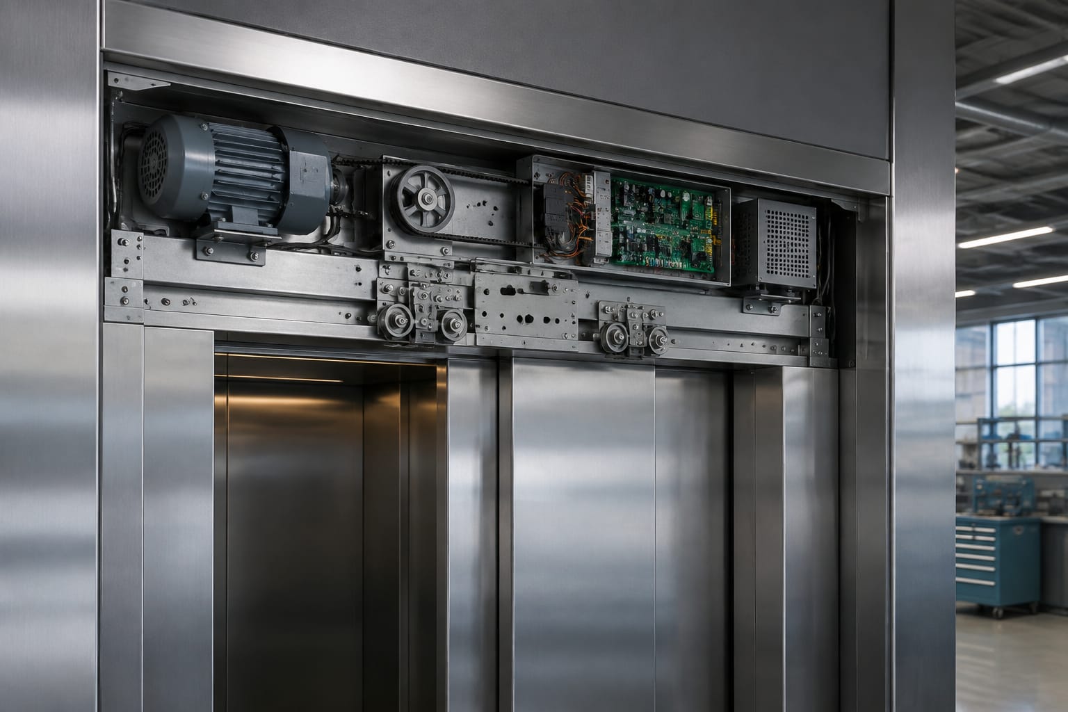
An elevator door drive is the coordinated system that opens, closes, reverses, and monitors elevator doors. It combines a motor, controller or drive board, mechanical transmission parts, feedback devices, and safety inputs. Reliable operation depends on matching these parts as a system, then completing correct mechanical adjustment and parameter setup.
For maintenance contractors and sourcing teams, the important question is rarely whether a replacement part looks similar. The replacement must match the original door operator’s electrical interface, motion profile, feedback method, safety circuit, mechanical arrangement, and required settings.
Parts of an elevator door drive
The term door drive can refer to the complete door operator or, more narrowly, the motor and electronic controller that power it. In a typical elevator installation, the door-drive system includes the following components:
- Door motor: Produces the rotational force used to move the car doors.
- Controller or drive board: Commands motor speed, direction, acceleration, deceleration, and stopping behavior.
- Transmission components: Belts, pulleys, gears, chains, couplings, or arms transfer motor motion to the door panels.
- Door hanger and track: Support the door panels and guide their travel.
- Clutch or vane assembly: Engages the landing-door mechanism when the car door opens and closes at a floor.
- Feedback device: An encoder, tachometer, Hall sensor, resolver, or other device tells the controller the motor position or speed.
- Open and close limits: Mechanical switches, magnetic sensors, encoder positions, or software limits establish end-of-travel positions.
- Safety inputs: Door edge, photoelectric curtain, obstruction sensor, lock monitoring, and related circuits provide safe reversal or inhibit unsafe movement.
- Power and wiring harnesses: Supply the drive and connect it to the car controller and door-safety chain.
The door operator is not isolated from the rest of the elevator. The car controller issues open and close commands, while door locks, safety devices, and position signals determine whether normal travel can continue. A problem that appears to be a door motor failure can therefore originate in wiring, a controller output, a door lock circuit, or excessive mechanical drag.
AC, DC, and PMSM door motors
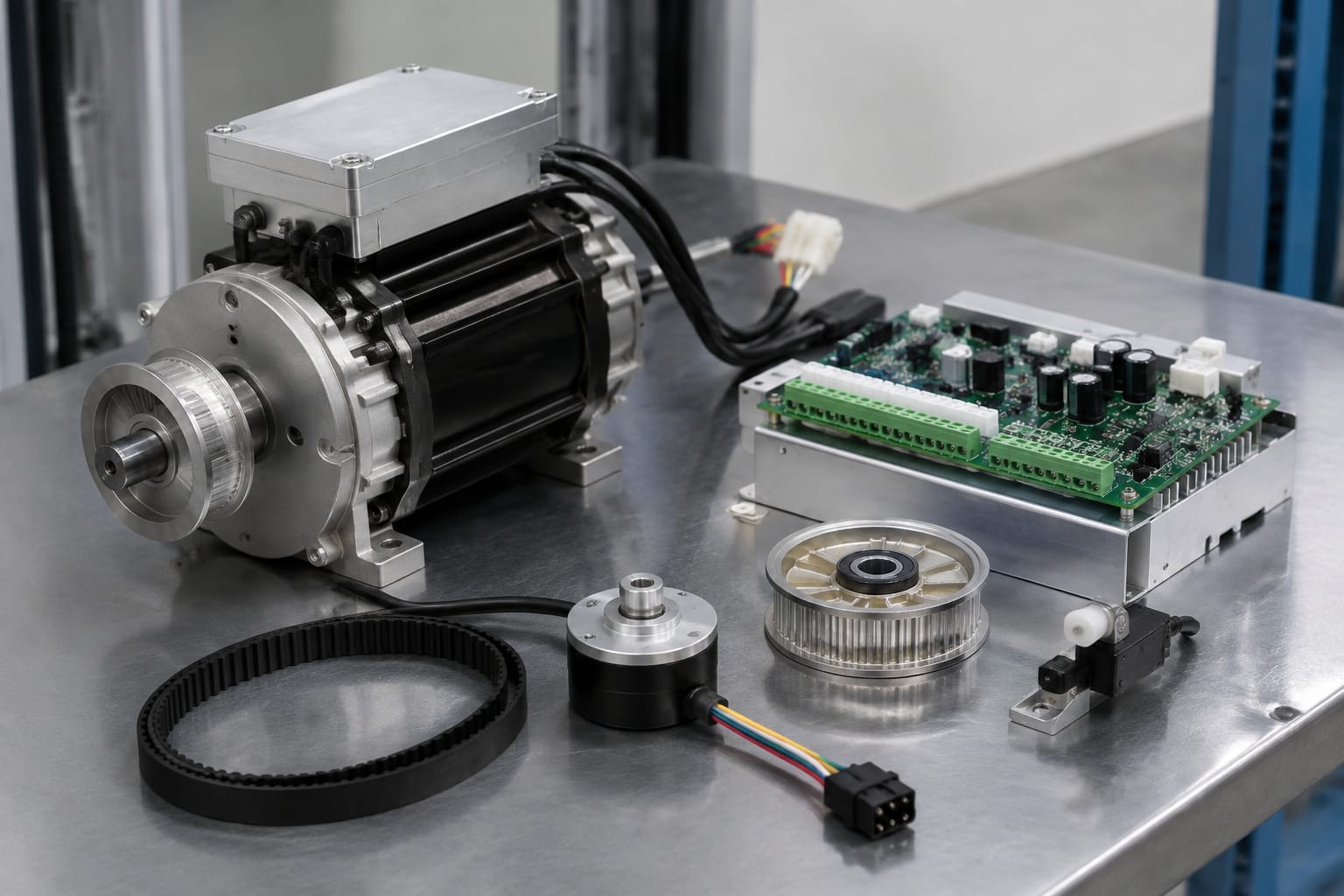
Door motors differ in supply type, control method, feedback requirements, and suitability for a particular operator design. The correct choice is determined by the original equipment and controller, not simply by the motor’s physical size.
| Motor type | Typical characteristics | Strengths | Key compatibility concerns |
|---|---|---|---|
| AC induction motor | Often paired with simpler control schemes or AC drive circuits | Durable construction and familiar service requirements | Voltage, frequency, winding configuration, capacitor arrangement where applicable, and rotation control |
| Brushed DC motor | Uses brushes and a commutator; common in many established door-operator designs | Direct speed control and straightforward reversal in compatible systems | Rated DC voltage, brush condition, polarity, armature characteristics, and tachometer or encoder interface |
| PMSM / brushless permanent-magnet motor | Electronically commutated motor, often used with dedicated drive electronics | Smooth low-speed control, efficient operation, and accurate motion control | Dedicated compatible controller, phase sequence, Hall or encoder feedback, and motor parameter data |
AC door motors
An AC door motor may be a single-phase or three-phase design, depending on the operator. Do not assume that an AC motor can be substituted with another AC motor of similar horsepower. The controller may depend on a specific motor winding, brake arrangement, sensor set, or speed-control method.
Verify the nameplate voltage and frequency against the elevator’s actual supply. In the United States, equipment may be designed around common building supply arrangements, but the specific door operator and controller documentation remains the controlling reference.
DC door motors
DC motors are common in door equipment because they can offer controllable low-speed operation and rapid direction changes. Their service requirements include inspection of brushes, commutator condition, wiring connections, and any attached feedback device.
Replacing a DC motor with a unit that has the same nominal voltage but a different feedback output or shaft configuration can cause poor door travel, controller faults, or immediate failure to run. The motor-controller pair must be considered together.
PMSM and brushless door motors
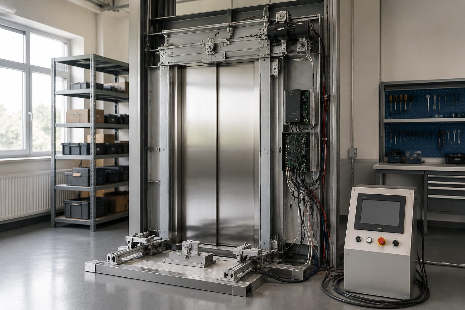
Permanent-magnet synchronous motors, often called PMSM or brushless motors, require electronic commutation. Their controller needs the correct motor-phase connections and position feedback. A motor can be mechanically correct yet unusable if the replacement drive cannot recognize its encoder, Hall sensors, or programmed motor parameters.
These systems can deliver controlled opening and closing behavior, but they are less forgiving of incorrect wiring, incompatible feedback, or copied parameter values from a different operator model.
Door controllers and drive boards
The controller is the decision-making and power-switching portion of the door drive. It receives commands and safety signals, energizes the motor, reads feedback, and regulates door motion.
Depending on the operator, the controller may be a separate electronic door drive, a board mounted in the door operator, or a module integrated into the car-controller system. Its functions commonly include:
- Motor direction control
- Speed regulation
- Opening and closing force management
- Acceleration and deceleration profiles
- Door dwell and nudging behavior when commanded by the car controller
- Obstruction reversal logic
- Limit detection and learned travel positions
- Fault reporting or diagnostic outputs
A replacement board must be compatible with the motor and the operator’s wiring architecture. This includes supply voltage, motor output type, connector layout, feedback input, sensor logic, safety-chain interface, and software or parameter set.
For examples of motor-and-board assemblies intended for specific equipment families, review relevant Hitachi door motor and drive board parts against the exact original identifiers and connection details. A product category or photograph is not sufficient proof of interchangeability.
Why board-only replacement can fail
A board replacement may not resolve the fault when the actual issue is elsewhere. Common causes include:
- A binding door panel or damaged hanger roller causing high motor current
- Broken conductors in the traveling cable or door harness
- A failed encoder, Hall sensor, or limit switch
- Incorrect parameter settings after replacement
- Poor grounding, loose terminals, or contaminated connectors
- A defective safety edge or light curtain that continuously signals obstruction
- An incompatible motor connected to the replacement board
Before condemning a board, identify whether it receives correct power and commands, whether safety inputs are in their expected state, and whether the motor and mechanics can move freely.
Feedback, limits, and safety sensors
Feedback and safety devices allow the door drive to know where the doors are, how fast they are moving, and whether an obstruction is present. A door operator cannot reliably regulate motion when these signals are missing, noisy, misadjusted, or incompatible.
Motor feedback
Feedback devices may provide speed information, position information, or both. Common examples include incremental encoders, Hall-effect sensors, tachometer generators, and resolvers.
Check these details before replacing a feedback-equipped motor:
- Connector type, pin count, and pin assignment
- Supply voltage to the sensor
- Signal type and expected pulse count or resolution
- Motor shaft orientation and coupling arrangement
- Shielding and grounding requirements
- Whether the controller requires a learned reference position after installation
Never interchange feedback devices based only on physical fit. Incorrect feedback can make the drive run erratically, move in the wrong direction, overshoot limits, or lock out on fault.
Limits and door-position signals
Older and simpler operators may use physical limit switches. Other systems use magnets and proximity sensors, encoder-based positions, or a combination of hardware and software limits.
Limit devices should be inspected for secure mounting, correct actuation point, wiring continuity, and repeatability. A close limit that operates too early can leave a gap or fail to establish correct door position. One that operates too late can drive the mechanism into a stop, increase wear, or produce a recurring fault.
Safety sensors
Door safety systems commonly include a door edge, light curtain, infrared detector, or another obstruction-detection device. They may command reversal during normal closing and may have different behavior during a programmed nudging sequence.
When diagnosing a repeated reopen condition, confirm the sensor’s status before changing controller parameters. A damaged lens, misaligned sensor, pinched cable, moisture, contamination, or incorrect supply voltage can create a false obstruction signal.
Safety circuits must remain functional after service. Do not bypass door protection, lock monitoring, or related safety inputs as a permanent troubleshooting method.
Common door-drive fault symptoms
Symptoms point toward a subsystem, but they do not prove the failed component. Start with observation, inspect the mechanical system, then measure and verify inputs before replacing parts.
| Symptom | Likely areas to inspect | Common mistake to avoid |
|---|---|---|
| Doors do not move | Incoming power, controller status, car-controller command, safety chain, harness continuity | Replacing the motor before confirming the drive has an enable command |
| Doors hum or attempt to move but stall | Door drag, belt tension, rollers, clutch interference, motor output, current limit | Increasing force settings to overcome a mechanical bind |
| Doors open or close slowly | Motor condition, controller parameters, supply voltage, friction, feedback | Treating a worn track or roller problem as an electronics failure |
| Doors reverse repeatedly | Light curtain, door edge, sensor wiring, close-force setting, mechanical interference | Disabling the obstruction input instead of finding the cause |
| Doors slam or overshoot | Deceleration settings, encoder/feedback quality, limits, belt condition, loose linkage | Adjusting limits without checking feedback and mechanical play |
| Door drive trips or displays a motor fault | Motor windings, insulation, phase/polarity, encoder, board output stage, wiring | Installing a board without checking the motor for an electrical fault |
| Intermittent failures | Traveling cable, door harness flex points, connector pins, ground, vibration | Assuming intermittent faults are software-related without a wiggle and continuity check |
A useful diagnostic sequence is: check physical freedom of movement, inspect visible components and connectors, verify power and command inputs, review fault indicators, test feedback and sensor states, then assess the motor and controller output. Follow the operator documentation and site safety procedures for all energized testing.
Match motor and controller specifications
The most important sourcing rule is to match the complete operating interface. A motor and controller are compatible only when their electrical, mechanical, feedback, and software requirements align.
Use the original labels, wiring diagrams, and operator documentation to create a comparison record before ordering.
Motor details to verify
- Manufacturer, model number, and any revision code
- Rated voltage, current, frequency, phase, and duty information
- AC, brushed DC, or PMSM/brushless motor design
- Rated speed and output characteristics where specified
- Shaft diameter, length, keyway, flats, and mounting pattern
- Gearbox, pulley, belt, or coupling compatibility
- Brake arrangement, if fitted
- Encoder, tachometer, Hall sensor, or other feedback type
- Feedback connector and pinout
- Rotation and phase/polarity requirements
Controller or drive-board details to verify
- Complete board or controller part number, including suffix and revision
- Input supply and output type
- Compatible motor family
- Connector count, keying, pinout, and harness arrangement
- Feedback and sensor interfaces
- Firmware, configuration plug, DIP-switch position, or parameter file requirements
- Communication interface with the car controller
- Physical mounting dimensions and heat dissipation requirements
- Fault-code and commissioning documentation
For a system where the drive board is an identified replacement item, compare the original part number with a Hitachi HGP door motor control board and verify the original operator application before purchase.
Do not rely on these shortcuts
Avoid selecting a replacement based only on:
- Similar appearance
- Connector style without pinout confirmation
- Similar voltage rating
- A motor’s mounting holes alone
- A partial part number
- A listing that names the same elevator brand but not the same door operator
- Assumptions that a newer board will retain old parameters automatically
Equipment revisions matter. A change in encoder type, harness wiring, software, or controller generation can make otherwise similar parts incompatible.
Parameter setup and mechanical alignment
Electronic setup cannot compensate for a poorly aligned door mechanism, and mechanical adjustment alone cannot correct unsuitable motion parameters. Both must be addressed after a door-drive repair or replacement.
Mechanical alignment first
With power isolated as required by site procedures, inspect and correct the following before commissioning:
- Confirm the door panels move smoothly through their travel without rubbing, binding, or excessive play.
- Inspect the track, hanger rollers, door shoes, belt or chain, pulleys, linkage, and clutch components for wear or damage.
- Verify belt tension or transmission adjustment according to the operator guidance.
- Check that the car-door clutch properly engages the landing-door equipment without striking or dragging.
- Set or verify door clearances, panel alignment, and final closed position.
- Confirm limit switches, magnets, or sensors are securely mounted and actuate consistently.
- Remove tools and ensure all guards, covers, and fasteners are restored before powered testing.
Adding force or extending the close time to mask friction can increase component wear and lead to nuisance faults. Fix the source of resistance first.
Typical controller parameters
Exact parameter names vary, but many door drives require setup of:
- Open and close direction
- Open and close speed
- Acceleration and deceleration
- Open and close travel limits
- Current or torque limits
- Obstruction reversal sensitivity
- Door dwell input behavior
- Nudging speed or force, where the system supports it
- Encoder direction, resolution, or reference position
- Motor-specific electrical data for compatible brushless systems
Record the original values before changing them when the existing system is operational. If values are unavailable, use the manufacturer-approved commissioning process rather than guessing from another door operator.
A replacement elevator door motor control board may require configuration after installation. Confirm whether parameter entry, a setup tool, a configuration device, or a learning cycle is needed for the specific board.
Commissioning the door system
Commissioning confirms that the repaired door drive operates predictably across its normal sequence and responds correctly to safety inputs. It should be completed by qualified personnel using the equipment documentation and applicable site procedures.
A practical commissioning checklist includes:
- Verify the replacement motor, board, harnesses, connectors, and grounding are correctly installed.
- Confirm the mechanism is free of tools, debris, loose hardware, and transport restraints.
- Apply power and check for normal controller status indications before commanding movement.
- Perform a controlled initial movement and immediately verify direction. Stop and correct wiring or settings if travel is reversed.
- Set or learn open and close positions as required by the operator.
- Adjust speed, acceleration, deceleration, and force values within the equipment’s approved range.
- Cycle the doors repeatedly and observe smooth travel, consistent stopping, and absence of abnormal noise or vibration.
- Test the door edge, light curtain, or other obstruction protection during closing.
- Verify landing-door engagement and closed-door condition at multiple landings where applicable.
- Confirm door lock and car-controller status signals operate correctly before returning the elevator to service.
- Document installed part numbers, parameter changes, fault history, and any remaining mechanical observations.
A door system that works on one cycle but varies between cycles is not fully commissioned. Intermittent feedback, marginal wiring, loose mechanical components, and inconsistent limits often appear only after repeated operation.
FAQ
Can an elevator door motor be replaced without replacing the controller?
Sometimes. A motor-only replacement may be appropriate when the controller has been verified as functional and the replacement motor is electrically, mechanically, and electronically compatible. However, a motor with a different feedback device, winding arrangement, or operating characteristics may require a matching controller or new configuration.
What causes an elevator door to reopen after it starts closing?
The most common causes are an active door edge or light curtain, an obstruction in the doorway, misaligned sensors, damaged sensor wiring, excessive mechanical resistance, or a controller setting that detects abnormal closing force. Inspect the safety input and mechanics before changing sensitivity settings.
Does a replacement door drive board need programming?
It may. Some boards use fixed hardware configuration, while others need learned travel limits, motor settings, parameter entry, firmware matching, or a configuration device. Confirm the commissioning requirements for the exact operator and board revision before installation.
Should a door-drive fault be solved by increasing closing force?
Not as a first response. Higher force can conceal worn rollers, a misaligned door panel, belt problems, or clutch interference. Correct the mechanical cause, verify sensors and feedback, and then set force only within the original equipment requirements.
For sourcing, collect clear photos of the motor and board labels, connector faces, wiring identifiers, feedback device, and door-operator assembly along with the fault description. Kelevator supplies multi-brand elevator spare parts for B2B buyers; those details provide a sound basis for confirming whether a proposed door-drive component fits the existing system.