
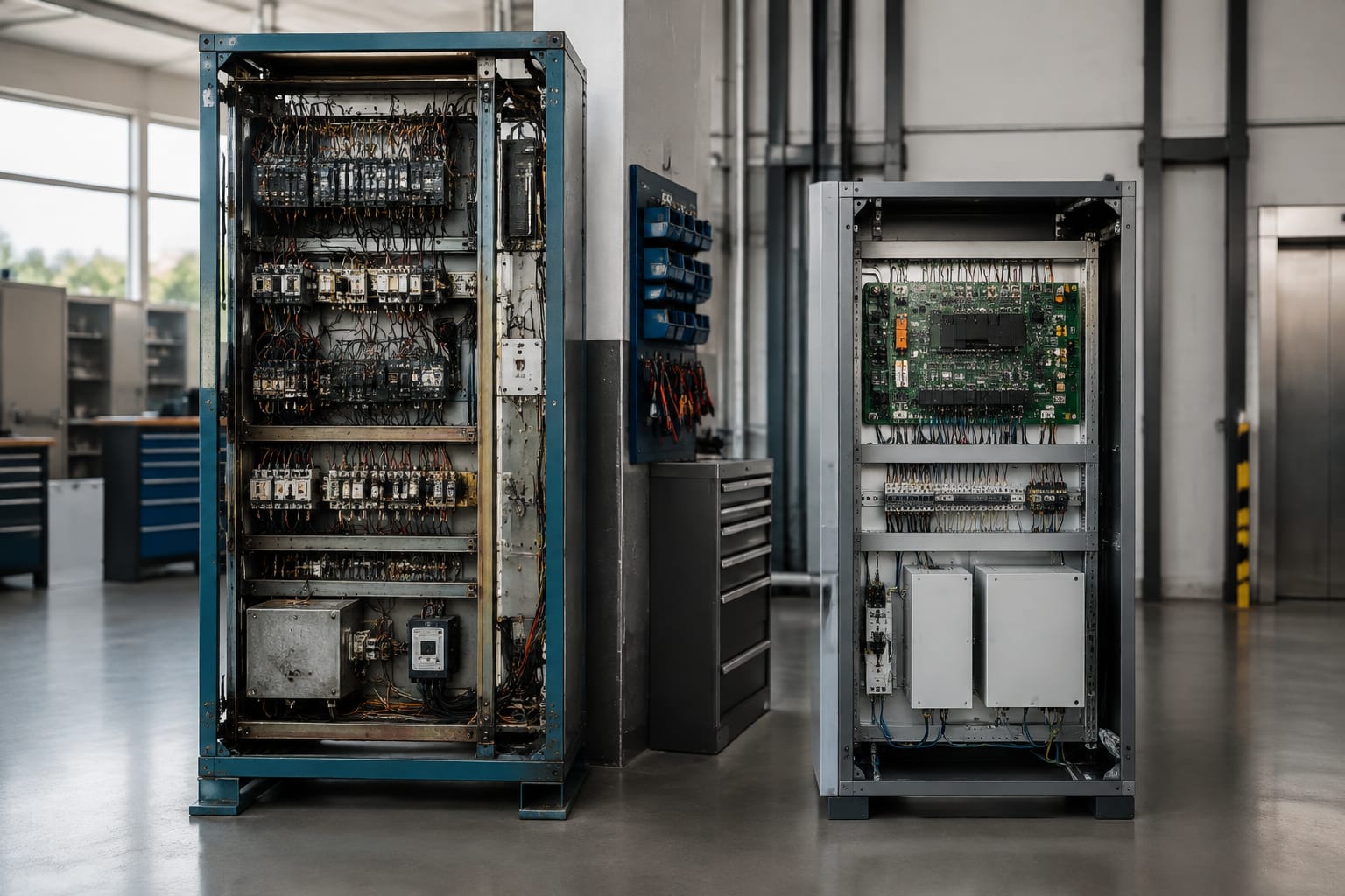
An elevator controller is the system that coordinates elevator movement, door operation, calls, safety monitoring, and communication with connected equipment. Choosing one is not simply a matter of matching the existing cabinet or drive: the replacement must fit the elevator’s machine type, motor and drive arrangement, door equipment, fixtures, safety circuits, and local code requirements.
For an in-kind replacement or modernization, start by documenting the existing controller and every connected interface. A controller that is technically capable but mismatched to the field wiring, encoder, door operator, or group system can turn a planned upgrade into an extended troubleshooting project.
What an elevator controller manages
The elevator controller is the decision-making and supervisory equipment for the elevator. It receives inputs from switches, sensors, buttons, and safety devices, then commands the drive, brakes, doors, indicators, and other outputs according to its programmed operating logic.
Its responsibilities commonly include:
- Registering car calls and hall calls, then dispatching the car appropriately
- Controlling acceleration, deceleration, leveling, stopping, and door-zone operation through the drive and motion feedback system
- Monitoring door locks, gate switches, safety-chain devices, and other conditions required before movement
- Operating door open, door close, nudging, reopening, and dwell-time functions
- Managing position information, floor selection, direction indicators, lanterns, and car displays
- Detecting faults, recording events, and presenting diagnostic information
- Supporting fire service, emergency power operation, inspection operation, and other required operating modes
- Exchanging data with door equipment, car-top devices, access-control systems, remote monitoring platforms, and, when applicable, other cars in a group
The scope differs by installation. A simple hydraulic elevator may use a controller with a straightforward single-car configuration, while a traction group installation may need coordinated dispatching, destination fixtures, networked displays, and extensive building interfaces.
A controller does not eliminate the need to evaluate the rest of the system. For example, unstable leveling can originate in the drive, encoder, hydraulic valve, sensor arrangement, or mechanical equipment. Replacing the controller without isolating the source of the problem may not correct it.
Relay-based, PLC, and integrated controls
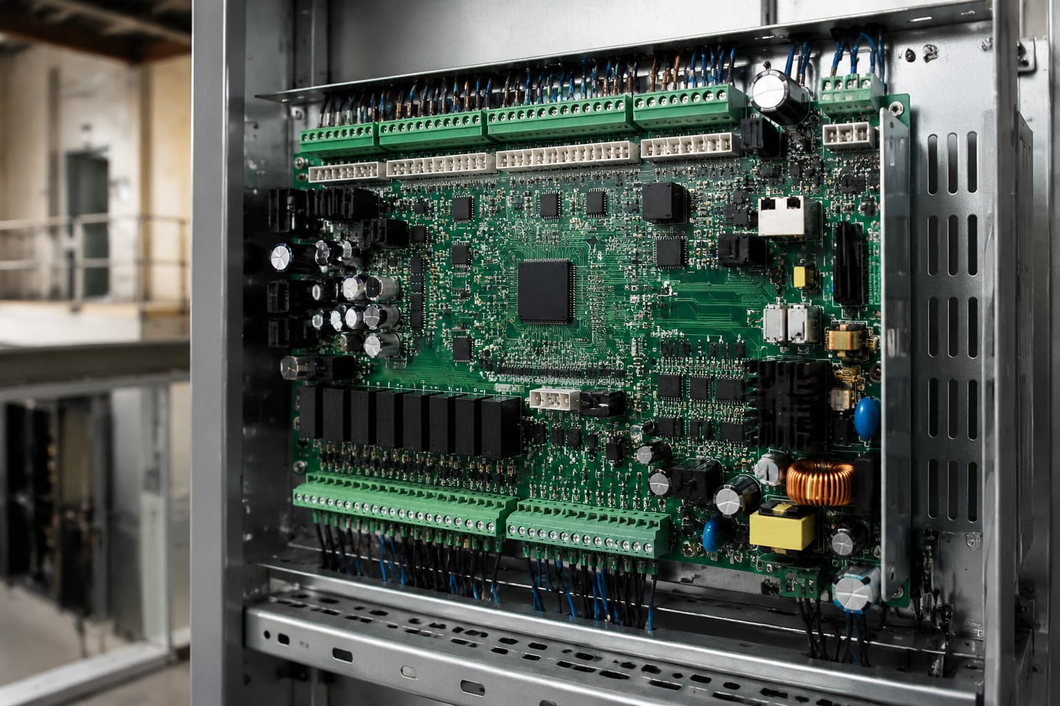
Elevator controls have evolved from relay logic to electronic boards and software-driven platforms. The right replacement approach depends on maintainability, available documentation, interfaces, code obligations, and the desired lifecycle of the equipment.
| Control approach | Typical characteristics | Advantages | Limitations and planning concerns |
|---|---|---|---|
| Relay-based controller | Electromechanical relays, timers, contactors, and extensive point-to-point wiring | Logic can be visually traced by experienced technicians; individual components may be replaceable | Large cabinets, aging contacts, limited diagnostics, difficult modification, and obsolete parts can make long-term maintenance impractical |
| PLC-based controller | General-purpose programmable logic controller with interface modules and custom programming | Flexible I/O architecture; familiar industrial components in some applications | Elevator-specific safety, motion, and code functions must be properly engineered; proprietary program access and documentation are essential |
| Integrated microprocessor controller | Dedicated elevator controller with application-specific boards, software, and diagnostics | Compact design, advanced diagnostics, configurable service features, support for serial fixtures and group operation | Board, firmware, protocol, and licensing compatibility may be manufacturer-specific; substitutes require careful validation |
| Hybrid modernization system | New controller retained with selected existing field equipment, fixtures, or drive components | Can target the highest-risk equipment while controlling project scope | Reused components may constrain functionality and create interface work; responsibility boundaries should be documented |
Relay control replacement versus modernization
A relay controller can sometimes be repaired where the failure is isolated and replacement components are available. That is different from determining whether repair is the best asset decision. Frequent relay failures, damaged wiring, unavailable diagrams, lack of diagnostic capability, or a need for newer operating functions often justify evaluating a modern controller.
Modernization does not always mean replacing every component. Existing fixtures, traveling cable, door operators, motors, or drives may be retained if their condition and interfaces are suitable. Each retained element should be treated as a compatibility decision, not an assumption.
PLC controls require elevator-specific discipline
A PLC can be part of an elevator control architecture, particularly in specialized or legacy applications. However, a generic PLC is not automatically a drop-in substitute for an elevator controller. The design must address safety-chain behavior, inspection operation, motion control interfaces, fault handling, applicable code requirements, and serviceability.
Before accepting a PLC-based solution, confirm who owns the program, how backups are maintained, what hardware revisions are supported, and how future technicians will access diagnostics. A system that cannot be commissioned or serviced without an unavailable programmer or undocumented logic presents a lifecycle risk.
Integrated controls and proprietary interfaces
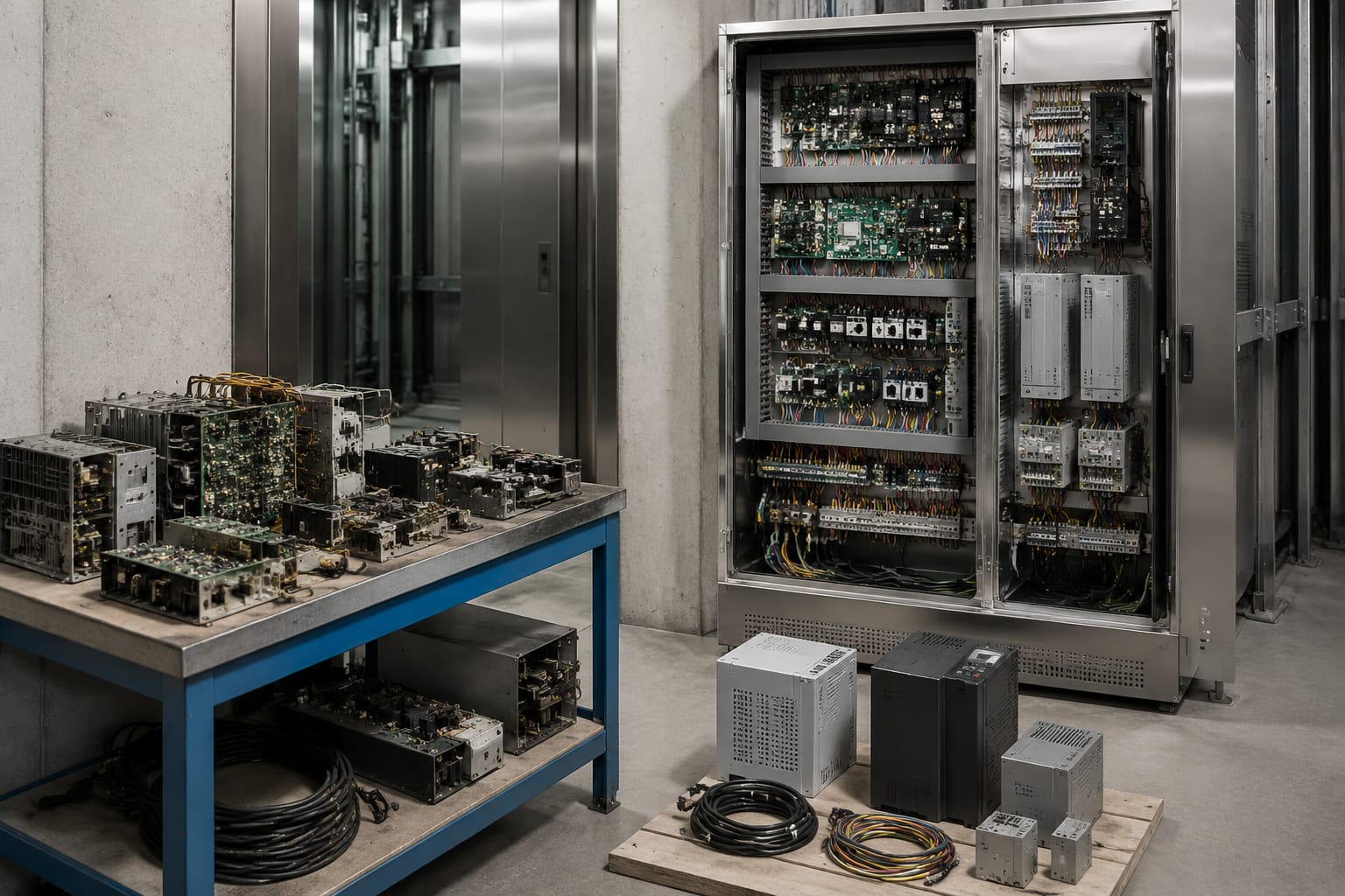
Integrated controllers commonly consolidate logic, diagnostics, serial communications, and configurable parameters. They can simplify cabinet wiring, but the connected equipment may use model-specific connectors, communication buses, firmware versions, or setup tools.
This does not rule out replacement with another platform. It means the project must explicitly account for translation or replacement of affected interfaces. The controller model alone is not enough to establish compatibility.
Traction versus hydraulic applications
The elevator’s machine and drive system strongly influence controller selection. A controller intended for traction use is not interchangeable with one designed around a hydraulic power unit unless its application support and hardware configuration explicitly cover the installation.
Traction elevator controller requirements
Traction elevators use a motor, brake, sheave, ropes or belts, and a drive or motor-control arrangement. The controller needs compatible control and feedback paths for those components.
Key items to verify include:
- Motor type, rated voltage, current, and speed
- Existing drive type and its commanded interface, such as discrete signals, analog reference, or serial communications
- Brake coil voltage, brake monitoring arrangement, and contactor configuration
- Encoder or position feedback type, resolution, mounting, and signal requirements
- Hoistway position system, including tape, magnets, selectors, switches, or encoder-based arrangements
- Machine-room, control-room, or machine-room-less installation layout
- Rescue, battery-lowering, or emergency-power operating requirements where applicable
- Single-car versus group-control requirements
Traction applications often demand close coordination between the controller and variable-voltage, variable-frequency drive. Confirm that the new controller supports the existing drive’s control mode and safety feedback, or include drive replacement in the modernization scope.
Hydraulic elevator controller requirements
Hydraulic elevators use a power unit that drives fluid to the cylinder and typically rely on different control outputs and landing behavior than traction systems. Hydraulic controller selection should address:
- Power-unit motor starter or soft-start configuration
- Valve coil voltages and valve-control wiring
- Up direction, down direction, leveling, and releveling functions
- Oil-temperature, pressure, low-oil, or other monitored conditions where installed
- Manual lowering, battery lowering, and emergency operation arrangements
- Hydraulic-specific timing and valve adjustment requirements
- Existing leveling system and landing sensors
A modern hydraulic controller may improve diagnostics and operational flexibility, but it cannot correct a valve, pump, cylinder, or mechanical issue by programming alone. Establish baseline performance before the work begins and preserve the original fault evidence.
Door and car-top control interfaces
Door equipment is one of the most common sources of controller-modernization complexity. The controller must work correctly with the car door operator, landing-door interlocks, door protection device, car-top inspection station, and traveling-cable circuits.
Door operator compatibility
Door operators may accept discrete open/close/nudge signals, use a dedicated interface board, or communicate digitally with the controller. Record the operator manufacturer, model, supply voltage, input type, output feedback, and any existing communication protocol.
Confirm these functions before selecting hardware:
- Door open and door close commands
- Door-open limit and door-closed/locked feedback
- Reopening signal from a light curtain, photo eye, or other protective device
- Nudging behavior and reduced-speed operation where required
- Door dwell time and independent-service behavior
- Fire service door behavior
- Fault indication and operator power supply requirements
A universal interface may reduce the amount of door hardware that must be replaced, but universal does not mean automatically compatible. Wiring diagrams and signal definitions still need to be compared. For projects involving certain Monarch STEP door arrangements, evaluate the available universal elevator multi-function operator parts against the documented equipment configuration.
Car-top equipment and inspection operation
The car-top station provides access to inspection controls and status information during service. The controller interface must support the installed inspection switches, stop switch, run buttons, direction controls, and safety devices.
During modernization planning, identify:
- Car-top inspection-station wiring and connector type
- Traveling-cable conductor count and condition
- Door-zone and leveling signals routed through the car
- Car-door operator power and control conductors
- Car-top access and stop-switch circuits
- Any load-weighing, seismic, unintended-car-movement, or other optional systems
Do not assume the existing traveling cable has sufficient spare conductors for a new hardwired fixture package. Serial car and hall communication can reduce conductor demand, but that choice affects fixtures, wiring topology, diagnostics, and replacement-part strategy.
Inputs, outputs, and safety circuits
Every controller replacement is ultimately an I/O mapping project. The controller must recognize every necessary field input and drive every required output, with the correct electrical characteristics and operating sequence.
Typical controller inputs
Inputs may include car and hall call buttons, door contacts, position sensors, limit switches, inspection controls, safety-chain contacts, drive status, fire service signals, emergency-power inputs, and fault feedback.
Document for each input:
- Device name and physical location
- Normal state and expected state during operation
- Voltage and whether the circuit is AC, DC, or low-voltage logic
- Contact type, polarity, and whether supervision is required
- Terminal number, wire identification, and related drawing reference
- Whether the signal is hardwired or transmitted over a communication bus
Typical controller outputs
Common outputs include motor or drive commands, brake control, door commands, car and hall indicators, buzzer or gong signals, fan and light controls, and relay outputs to building systems.
For outputs, verify the required voltage, current, load type, suppression needs, and whether an interposing relay is necessary. A controller output intended for a logic input should not be used directly to drive a coil or other load beyond its rating.
Safety circuits are not a routine I/O exercise
The safety chain and related protective circuits are critical to elevator operation. Their configuration can vary by application, equipment generation, and jurisdiction. A controller modernization must preserve or properly redesign required safety functions, including the relationship between the controller, door locks, stop switches, governor and pit devices, terminal limits, brake monitoring, and other protective components.
Do not bypass a safety device to make a new controller run during testing. Temporary jumpers can conceal wiring errors and create serious hazards. Commissioning should use documented test procedures performed by qualified elevator personnel and in accordance with applicable codes and authority requirements.
Selecting replacement controller hardware
The best replacement controller is the one that matches the application, supports the desired modernization scope, can be commissioned with available documentation, and remains practical to service. It is rarely the controller with the longest feature list.
Use this selection checklist before requesting or purchasing hardware:
- Define the project type. Is the need a repair, an in-kind controller replacement, a controller-and-drive package, or a broader modernization?
- Identify the elevator application. Confirm traction or hydraulic operation, number of stops, travel, speed, capacity, machine configuration, and single-car or group operation.
- Capture the existing equipment data. Photograph controller labels, drive labels, wiring terminations, car-top station, door operator, fixtures, and hoistway position equipment. Record model and revision numbers accurately.
- Create a complete interface list. Include power supply, motor controls, brakes, valves, encoders, selectors, doors, fixtures, fire service, emergency power, monitoring, and access control.
- Compare electrical requirements. Check supply voltage, phase, control voltage, coil ratings, fuse or breaker arrangements, grounding, and available cabinet space.
- Review fixture strategy. Decide whether to reuse existing car operating panels and hall stations, add interface boards, or replace fixtures with a serial system.
- Confirm diagnostic access. Verify what tools, passwords, software, parameter files, and service documentation are needed to install and maintain the new controller.
- Evaluate supportability. Ensure that replacement boards, fuses, relays, interface modules, and communication components can be identified and sourced over the expected service life.
- Plan code and inspection work. The scope may trigger permitting, acceptance testing, or additional upgrades. Requirements should be reviewed with the responsible local parties before installation.
- Protect the configuration record. Require final drawings, parameter backups, software versions, terminal schedules, and passwords to remain accessible to the owner or authorized maintenance provider.
For systems that integrate tenant or credential-based entry, confirm the controller’s access-control interface rather than treating it as an afterthought. Depending on the architecture, a project may need a compatible elevator access-control motherboard or another elevator access-control board and motherboard option designed around the existing system requirements.
Planning a controller modernization
A well-planned modernization begins with a survey and ends with verified operation, not simply a cabinet swap. The controller should be specified only after the existing equipment and project boundaries are clear.
Establish the modernization scope
Separate work into three categories:
- Replace: Equipment that is obsolete, unreliable, incompatible, damaged, or necessary to meet the intended operating requirements
- Retain: Equipment that has been inspected and can work with the proposed controller
- Interface: Equipment that will stay in place but needs adapters, relays, new wiring, programming, or communication conversion
This classification exposes hidden cost and risk. For instance, retaining hall fixtures may require fixture interface modules; retaining an old drive may require a compatible command card and feedback wiring; retaining a door operator may require a relay package or dedicated interface.
Avoid common planning mistakes
Several mistakes repeatedly create avoidable field delays:
- Ordering from a controller part number without confirming the elevator application and connected equipment
- Treating an existing wiring diagram as current without field verification
- Omitting drive, encoder, brake, or valve details from the submittal package
- Reusing fixtures without checking lamp, button, communication, and wiring compatibility
- Overlooking traveling-cable capacity and deterioration
- Failing to preserve parameter settings before removing the old controller
- Assuming an access-control, monitoring, or fire-alarm connection will continue to work unchanged
- Leaving responsibility for final programming, testing, and documentation undefined
A pre-installation survey should result in a clear terminal mapping, bill of materials, wiring plan, sequence-of-operation plan, and list of unresolved site conditions. This preparation is especially important when sourcing multi-brand spare parts through distributors or import channels, where an accurate identification package prevents unnecessary substitutions.
Decide whether to retain the existing drive
Retaining a serviceable drive can reduce scope, but only when compatibility is demonstrated. Verify command method, speed-reference scaling, run and fault contacts, brake coordination, encoder handling, and required parameter access.
Replace the drive as part of the project when it is obsolete, unreliable, incompatible with the new controller, lacks supportable diagnostics, or limits the intended performance. A combined controller-and-drive modernization can simplify responsibility for the motion-control interface, though it increases the initial project scope.
Commissioning and documentation
Commissioning is the stage where a correct hardware selection becomes a dependable operating system. It should follow an organized sequence, with records created as each function is confirmed.
Commissioning sequence
A practical sequence typically includes:
- Verify incoming power, grounding, protection, cabinet wiring, and labeling before energizing equipment.
- Confirm safety-chain continuity and the correct operation of stop switches, door locks, pit devices, terminal devices, and other applicable protective circuits.
- Validate controller configuration against the elevator’s documented application, including floors, travel direction, speed, door timing, and service modes.
- Test machine or power-unit control, brake or valve operation, direction, and feedback at low-risk stages before normal service operation.
- Set up and verify floor position, leveling, door-zone operation, terminal stopping, and releveling as applicable.
- Test car calls, hall calls, indicators, gongs, displays, and fixture operation at every landing.
- Verify door protection, reopening, nudging, dwell timing, and fire-service behavior.
- Test inspection operation, emergency power functions, communication interfaces, and building-system connections within the project scope.
- Review fault logs and correct wiring, parameter, or interface errors before turnover.
- Complete required inspections, tests, and records before returning the elevator to normal service.
Specific test obligations vary by equipment and jurisdiction. The commissioning team should use the applicable code requirements, manufacturer instructions, and site-approved procedures rather than relying on a generic checklist alone.
Deliver the information needed for future service
The final documentation package should include updated wiring diagrams, terminal schedules, controller and drive settings, software and firmware versions, backup files, fault-code references, equipment labels, and a list of replaced and retained components.
Keep copies where the maintenance provider can access them. A controller may remain in service for many years; missing passwords, undocumented parameter changes, or inaccurate drawings can turn ordinary troubleshooting into a prolonged outage.
FAQ
Can any elevator controller replace an older controller?
No. A replacement must be appropriate for the traction or hydraulic application and compatible with the drive or power unit, motor controls, position system, doors, fixtures, safety circuits, and required building interfaces. An adaptable controller may still require interface hardware, rewiring, or component replacement.
Is it possible to keep the existing elevator fixtures?
Often, yes, but compatibility must be verified. Older fixtures may use discrete wiring, while newer controllers may be designed for serial fixtures. Evaluate voltage, lamp or display type, button contacts, communication protocol, traveling-cable capacity, and the cost of interface hardware against fixture replacement.
Does replacing the controller improve ride quality?
It can, particularly when the controller and drive arrangement are upgraded and properly tuned. However, ride quality also depends on the motor, drive, encoder, brake, guide system, ropes or belts, hydraulic valve, and mechanical condition. Diagnose those factors before promising a performance result.
What information should be sent to a controller supplier?
Provide clear photos and model information for the existing controller, drive or power unit, motor, door operator, car-top equipment, fixtures, and position system. Include wiring diagrams, voltage details, number of stops, travel, speed, known faults, required service features, and the intended retain-versus-replace scope.
A controller replacement is most successful when it is treated as a complete interface and documentation project. Kelevator supplies multi-brand elevator spare parts for B2B buyers; use a complete equipment record and verified part identifiers when evaluating controller-related boards, interfaces, and modernization components.
Related product references
For practical catalog examples related to this topic, review 5500 elevator acess control board motherboard ID lift parts, Elevator Access Control Board motherboard lift accessories, and Universal elevator multi-function operator Monarch STEP system elevator parts. Confirm the exact model, dimensions, ratings, and connectors before ordering.