
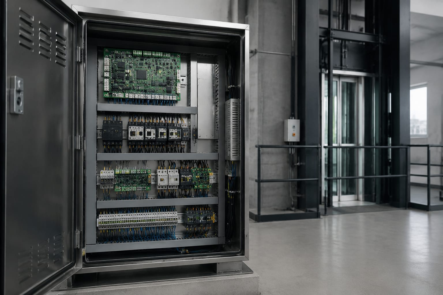
An elevator control panel is the control system that receives car and landing requests, monitors safety inputs, commands the drive and door equipment, and records operating status. Depending on the elevator design, it may refer to the controller cabinet in the machine room or control space, a car operating panel, or a specific electronic board within either assembly.
When a panel-related problem occurs, replacing the first board that appears suspect can create unnecessary cost and downtime. A practical repair process starts by confirming the symptom, power quality, safety chain state, wiring, configuration, and part compatibility. Replacement becomes appropriate when a board is demonstrably failed, damaged, unsupported, or no longer reliable after repair.
What an elevator control panel does
The elevator controller coordinates the equipment needed to move a car safely from floor to floor. It interprets inputs, applies programmed operating logic, and energizes outputs only when required conditions are met.
Typical controller functions include:
- Receiving car calls, hall calls, door-zone signals, and floor-position information
- Starting, stopping, leveling, and dispatching the car
- Sending run and speed-related commands to the drive system
- Operating door open, close, reopen, and nudging sequences
- Monitoring the safety circuit and related protective devices
- Managing inspection, independent service, fire service, emergency power, and other configured modes
- Communicating with car fixtures, landing fixtures, displays, remote monitoring equipment, or group controls
- Recording faults, operating events, and diagnostic status
The term elevator control panel is also used loosely. Before ordering a replacement, identify which assembly is actually involved:
| Assembly | Typical location | Primary role | Common issue |
|---|---|---|---|
| Main controller board | Controller cabinet | Executes operating logic and manages I/O | Persistent faults, lost inputs or outputs, processor errors |
| Power supply board or module | Controller cabinet | Produces regulated DC voltages | Intermittent resets, dead displays, unstable relays |
| Drive interface board | Controller or drive equipment | Exchanges run, direction, speed, and status signals | Car will not run despite healthy logic |
| Door control board | Car door operator or controller | Controls door motor and door protection sequence | Doors fail to open, close, or reverse correctly |
| Car operating panel electronics | Inside the cab | Processes buttons, indicators, and fixture communications | Unresponsive buttons, dark indicators, missing floor selections |
| Voice or annunciator board | Car panel or controller | Generates audible messages and alarm-related audio | No floor announcements or distorted audio |
A symptom at the car operating panel does not necessarily mean the car panel is defective. For example, dark indicators may result from a missing low-voltage supply, a failed communication link, an open harness connection, or a controller configuration issue.
Main boards and power components
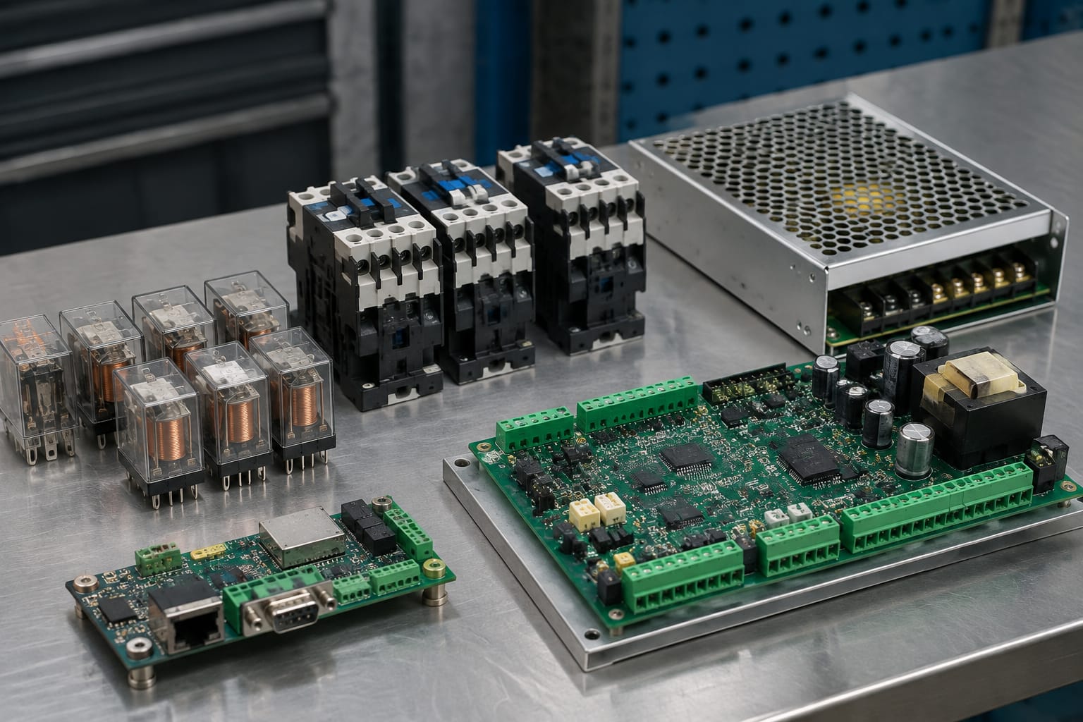
The main control board is the decision-making element in many elevator controllers. It commonly contains a processor, memory, input and output circuits, status LEDs, service connections, and interfaces for expansion boards. Some systems integrate most functions into one board; others distribute them across a CPU board, I/O boards, drive interface boards, and serial communication modules.
Controller CPU and I/O boards
A CPU board runs the programmed operating logic. It uses information from sensors, switches, fixtures, and safety-related circuits to determine whether the car can move and what action should occur next.
I/O boards convert field signals into information the controller can use and send outputs back to relays, contactors, indicators, door equipment, and other devices. An I/O failure can resemble a field wiring problem because a single input may remain inactive or a single output may never energize.
Before condemning an I/O board, compare the board LED state, terminal voltage, schematic expectation, and actual device condition. A failed limit switch, broken conductor, loose terminal, or damaged plug can produce the same visible symptom as a failed input channel.
Power supplies and backup power
Electronic controls depend on stable power. A power supply may provide several regulated DC outputs for logic, communications, fixtures, relays, and door equipment. Aging capacitors, heat stress, loose terminals, grounding problems, or incoming-voltage issues can cause voltage sag or excessive ripple.
Common power-related symptoms include:
- Controller resets or loses position intermittently
- LEDs flicker or displays dim when outputs energize
- Multiple unrelated communication faults appear together
- Relays chatter instead of pulling in cleanly
- The controller powers up but does not complete startup
- A fault only occurs during high-demand events, such as door operation
Check the voltage at the supply output and, when practical, at the affected board under operating load. A correct reading at an unloaded power supply does not prove the circuit remains stable when relays, indicators, or communication equipment are active.
Backup batteries or emergency lowering power sources also need separate evaluation. A depleted battery may not affect normal operation but can prevent expected emergency behavior or create low-voltage alarms.
Relays, contactors, and safety circuits
While modern controllers use more electronic logic than older relay-based systems, relays and contactors remain important in many installations. They switch higher-current loads, isolate circuits, and provide status feedback. Mechanical components wear differently from circuit boards, so their diagnosis should be based on contact condition and measured performance rather than appearance alone.
Relays and contactors
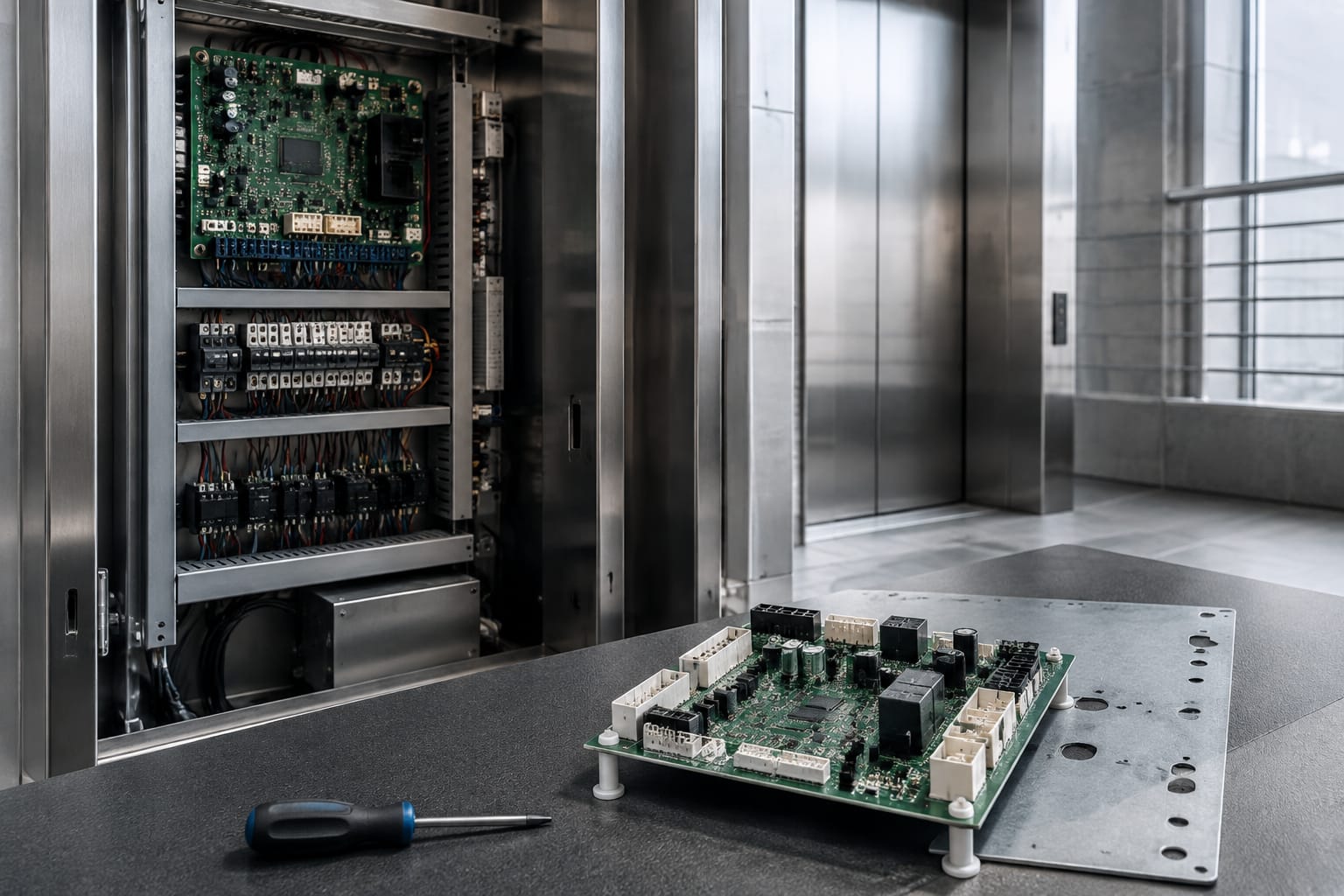
A relay coil can energize while its contacts fail to carry current reliably. Contactors can develop pitting, welding, contamination, weak coil operation, or mechanical binding. A controller output LED may show that a command was issued, yet the downstream device may remain inactive because the relay or contactor did not transfer the command.
Inspect and test for:
- Correct coil voltage when commanded
- Secure terminals and properly sized conductors
- Contact continuity and voltage drop under load
- Heat discoloration, burned insulation, or damaged contact surfaces
- Mechanical movement and proper auxiliary-contact feedback
- Correct replacement coil voltage, contact arrangement, and load rating
Do not substitute a relay based solely on its physical footprint. Coil voltage, AC or DC operation, contact form, contact rating, suppression requirements, and pinout all matter.
Safety circuit inputs
The safety circuit is designed so that certain protective devices must be in the correct state before the elevator can run. Depending on the equipment and configuration, this can include stop switches, governor and safety-device contacts, door and gate contacts, pit devices, top-of-car devices, inspection switches, and other required protective contacts.
An open safety chain is usually a condition to diagnose, not a board-replacement diagnosis. The controller may display a safety-related code, but the root cause can be a field device, alignment issue, damaged wiring, failed contact, or an incorrect state caused by inspection or service mode.
Technicians should follow the equipment documentation and site procedures for safe troubleshooting. Never bypass, jumper, or defeat a safety circuit to restore normal service. Temporary diagnostic methods, where permitted by the manufacturer and applicable procedures, require competent personnel and must be removed before returning the elevator to service.
Communication and voice boards
Elevator systems increasingly use serial or networked communication instead of individual conductors for every fixture function. A communication board may connect the controller to car stations, hall stations, displays, door equipment, group systems, or remote interfaces. A voice board may provide floor announcements, direction messages, alarm audio, and other audible functions.
For systems using a dedicated announcement module, the relevant item may be a VCA-11-QD elevator control panel voice board. The model and application still need to be verified against the installed equipment before purchase.
Communication faults often create patterns:
- Several car buttons or indicators fail together
- One fixture works while another on the same bus does not
- The controller logs intermittent communication loss
- Displays show incorrect, frozen, or missing information
- Faults change after harness movement, door travel, or vibration
- Audio is missing while normal car operation remains intact
Start with bus power, polarity, termination requirements, connector seating, shield or grounding practice where applicable, and visible cable damage. A shorted or incorrectly connected device can disrupt a shared communication line and make multiple healthy devices appear defective.
Voice-board faults need additional separation from speaker, wiring, amplifier, volume setting, message storage, and controller command issues. No announcement does not automatically mean the voice board has failed.
Common control-panel fault symptoms
Symptoms can point toward a section of the control system, but they rarely identify a single failed component without testing.
| Symptom | Likely areas to check first | Replacement may be justified when |
|---|---|---|
| Controller is completely dead | Incoming power, disconnects, fuses, transformer, power supply, terminals | Correct input power is present and the supply or board has failed output testing |
| Repeated controller resets | DC supply stability, grounding, heat, harnesses, CPU board | Supply and wiring are confirmed stable and board-level failure is verified |
| Car will not run | Safety chain, drive status, inspection state, position signals, run outputs | Required inputs are proven correct but the control output is absent or defective |
| Doors will not close or reopen unexpectedly | Door operator, protection devices, door locks, car-top wiring, door control board | Field devices and harnesses test correctly and board command/output failure is confirmed |
| Buttons or displays are dead | Fixture power, traveling cable, serial bus, car panel electronics | Correct power and communication reach the fixture but its electronics remain unresponsive |
| One output remains on or off | Field load, relay or contactor, output fuse, output channel | Load and wiring are isolated and the output channel does not respond correctly |
| Erratic fault codes | Supply voltage, grounding, connectors, moisture, heat, configuration | Environmental and connection causes are eliminated and diagnostics support board failure |
| No voice announcements | Speaker, wiring, volume/configuration, voice board | The command and power are present but the board produces no valid audio |
A visual inspection helps, but it is not conclusive. Swollen capacitors, burnt areas, corroded connectors, broken solder joints, and water damage are meaningful evidence. Many electronic failures leave no visible trace, while a discolored board can still function. Measurements and fault history should drive the decision.
Diagnostic checks before replacement
A disciplined diagnostic sequence reduces unnecessary replacements and makes a replacement order more accurate. Always use the equipment documentation, lockout procedures, and qualified personnel appropriate for the work.
1. Capture the condition before cycling power
Record active fault codes, status LEDs, car position, service mode, drive status, and the exact symptom. If an intermittent problem disappears after power cycling, the original fault record may be the most useful evidence available.
Note what triggers the issue: a particular landing, door cycle, direction, fixture, temperature condition, or period of operation. Repeatable conditions are more valuable than a broad description such as “intermittent.”
2. Verify incoming and low-voltage power
Check fuses, disconnects, terminals, transformer outputs, regulated DC supply outputs, and grounds. Measure expected voltage where the affected board receives it, not only at the upstream source.
Look for loose terminals, heat damage, signs of moisture, and changes in voltage when the affected function is commanded. Treat exposed energized equipment as a serious hazard and follow site safety practices.
3. Confirm the controller’s input view
Use controller diagnostics, LED indicators, or approved service tools to compare what the controller sees with the actual field-device state. If a door lock is physically closed but the input never changes, determine whether the fault is in the contact, wiring, connector, input voltage, or board channel.
Do not assume an input is valid merely because a component looks normal.
4. Trace outputs to the field device
When the controller commands an output, verify whether voltage reaches the relay coil, contactor, door operator input, indicator, or other load. If the controller output changes but the load does not respond, continue downstream. If the controller does not issue the output despite all required conditions being present, investigate logic, configuration, interlocks, and the output board.
5. Inspect connectors and harnesses
Reseat connectors only with appropriate power isolation and procedures. Check for bent pins, backed-out terminals, corrosion, insulation damage, strain at moving points, and harness routing that allows vibration or abrasion.
For car fixtures, the traveling cable and door-travel wiring deserve particular attention. Movement-related faults frequently originate in conductors or connectors rather than the controller cabinet.
6. Review configuration and fault history
A replacement board may require software, parameter, floor-table, drive, door, fixture, or communication settings. Confirm that a reported problem is not caused by an altered setting, incorrect job data, or a mismatch after earlier service work.
If a board was swapped previously, confirm that it is the intended revision and has the required configuration. An otherwise healthy board can behave incorrectly when installed with incompatible parameters.
Board and connector compatibility
The correct-looking elevator control panel board is not necessarily an interchangeable replacement. Electrical, mechanical, software, and system compatibility all need confirmation.
For a controller motherboard, use the complete installed part number and revision rather than a broad family description. A 5400 elevator control motherboard may be relevant when that exact system family is installed, but buyers should validate the board identification, revision, connectors, and required programming before treating it as a direct substitute.
Use this compatibility checklist before ordering:
- Exact manufacturer part number, board number, and revision level
- Controller model, system generation, and installed software or firmware version
- Connector count, connector keying, pinout, and harness orientation
- Supply voltage and any required auxiliary voltages
- Input and output type, including AC/DC levels and sinking or sourcing arrangement where applicable
- Communication protocol, bus address, termination, and fixture compatibility
- Required firmware, configuration file, parameter set, or licensing process
- Physical dimensions, mounting points, heat-sink arrangement, and enclosure clearance
- Whether the board is new, repaired, exchange, refurbished, or a functional equivalent
- Return, core, programming, and testing requirements set by the supplier
Door controls need the same care. Door operator boards vary by operator model, motor type, encoder arrangement, supply voltage, connector layout, and software settings. A Toshiba elevator door control panel should be selected by matching the installed equipment details, not merely by matching the elevator brand.
Common compatibility mistakes include ordering from a photo, overlooking a suffix on the part number, transferring a board without checking jumpers or settings, and assuming a newer revision is backward compatible. A clear photo of both sides of the installed board, readable labels, connector details, controller identification, and the recorded fault condition improves sourcing accuracy.
Commissioning repaired or upgraded controls
Replacing a board is only the midpoint of the work. Commissioning verifies that the controller, connected equipment, and safety functions operate as intended with the installed configuration.
Before energizing the system, inspect mounting hardware, connector seating, grounding, wire routing, fuses, jumpers, and any transported configuration media. Confirm that the replacement board is suitable for the controller and that no packing material, loose fasteners, or damaged terminals remain in the cabinet.
A practical commissioning sequence includes:
- Verify the board identity, revision, and configuration against the controller documentation.
- Power up using approved procedures and check supply voltages, status indicators, and diagnostic startup messages.
- Confirm that safety-related inputs and service modes display correctly without bypassing protective circuits.
- Test car calls, hall calls, leveling, direction operation, door cycles, and affected fixtures within the approved test process.
- Verify drive interface status, position information, door protection behavior, and communication with connected devices.
- Test required building or emergency operation modes according to the equipment documentation and applicable site requirements.
- Review fault history after testing, document the installed part and settings, and return the elevator through the required release procedure.
For a modernization, commissioning may be broader because the new controls can interact with retained motors, drives, door operators, fixtures, wiring, and building interfaces. Identify what remains from the prior system and who owns configuration, field adjustment, acceptance testing, and documentation. A modern control package cannot compensate for unresolved wiring, door, drive, or mechanical conditions.
For contractors and sourcing teams, the strongest replacement decision is supported by a recorded fault, measured checks, exact board identification, connector verification, and a commissioning plan. Kelevator supplies multi-brand elevator spare parts for B2B buyers; when sourcing a component, provide those details so the proposed part can be evaluated against the installed system.