
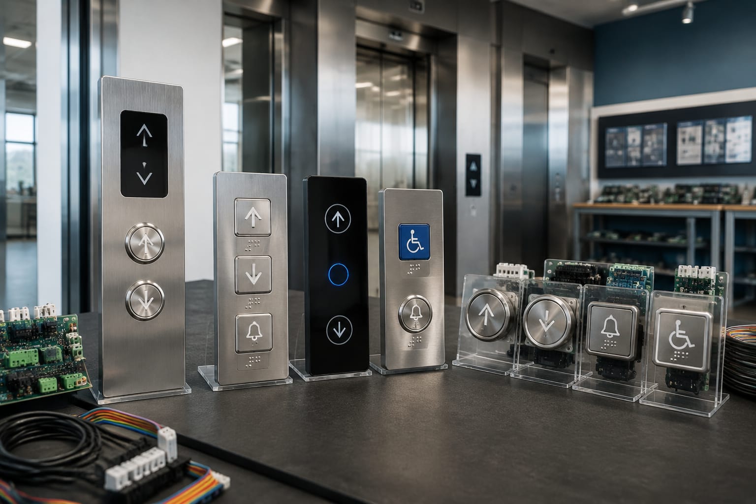
Elevator buttons are the passenger-facing controls that register a floor selection, door command, alarm request, or landing call. Although they appear simple, a correct replacement depends on more than the button’s visible shape. Its mounting dimensions, electrical contacts, illumination method, voltage, tactile markings, wiring or board interface, and controller compatibility all matter.
For maintenance and modernization work, first determine whether the control is a car operating panel button or a landing call button. Then match the original part by function and interface before comparing appearance. A similar-looking elevator push button can fail to communicate correctly, illuminate improperly, or not fit the panel.
Car operating and landing call buttons
Car operating panel (COP) buttons are installed inside the elevator cab. They let passengers select a destination floor and operate functions such as door open, door close, alarm, and emergency communication. A COP may also include key switches, a display, fire service controls, and an access-control reader.
Landing call buttons are installed outside the elevator at each floor. Their job is narrower: they request travel in the up or down direction. In a conventional two-button hall station, the up button is used below the desired travel direction and the down button above it. A single-button hall station may be used where only one travel direction is available or where the landing configuration calls for it.
The button’s signal is interpreted differently depending on its location:
| Control location | Typical buttons | What the signal requests | Key replacement concern |
|---|---|---|---|
| Car operating panel | Floor numbers, door open/close, alarm, phone | A selected destination or car function | COP layout, controller input type, accessibility markings |
| Hall or landing station | Up, down, occasionally both directions on one unit | A request for a car traveling in the selected direction | Station configuration, call system and wiring |
| Service or restricted panel | Keyed floor buttons, independent service, attendant controls | Authorized or special operation | Key type, control logic, permitted function |
A lit floor button in the cab usually confirms that the elevator has accepted a car call. At the landing, an illuminated arrow generally confirms a registered hall call, though the exact feedback behavior depends on the building’s control system. It does not necessarily mean the car is immediately arriving.
Why car and landing buttons are not interchangeable
A floor button and an up-arrow button may use a comparable physical switch mechanism, but their faceplates, legends, illumination, mounting, and electrical connections often differ. Hall buttons can also be part of a proprietary fixture system or an integrated hall station assembly.
Do not treat a matching diameter as proof of compatibility. A replacement must match the original operating role and the equipment interface.
Common elevator button symbols
Symbols should communicate a function quickly, especially during normal operation, an emergency, or an accessibility-related use case. The exact icon style can vary by manufacturer and fixture generation, but several symbols are widely recognized in U.S. elevator installations.
| Symbol or marking | Usual function | Practical note |
|---|---|---|
| Number or letter | Selects a floor | Letters can identify lobby, parking, roof, or other designated levels. |
| Up arrow | Registers an upward hall call | Indicates desired travel direction, not a specific floor. |
| Down arrow | Registers a downward hall call | Typically installed with an up button where both directions are available. |
| Two arrows pointing apart | Door open | Keeps doors open or reopens them while conditions allow. |
| Two arrows pointing together | Door close | Requests door closing; safety devices can prevent closing. |
| Bell | Alarm | Activates the car alarm circuit. |
| Telephone handset | Emergency phone | Connects to the required emergency communication system when equipped. |
| Star | Main egress floor designation | Commonly identifies the designated main egress level. |
| Firefighter’s hat or fire-service marking | Fire service control | Usually associated with a key switch or dedicated service control, not normal passenger operation. |
Door-control icons are frequently misunderstood. Pressing door close does not override the door safety system, and door open does not guarantee the doors will remain open indefinitely. The controller still applies programmed timing and safety conditions.
Floor labels need attention during replacement. A “G,” “L,” “1,” or “M” label may all represent a primary entry level depending on the property. Replacing a damaged button with the wrong legend creates a wayfinding issue even when the electrical part works correctly. Confirm the existing building designation, not merely the physical floor number.
Tactile markings and Braille
In U.S. passenger elevators, tactile characters and Braille are important functional requirements, not cosmetic details. They support use by people with visual disabilities and should be retained during a fixture repair or modernization. Verify the character format, location, contrast, and raised features against the applicable project requirements and governing code.
A replacement button with a printed numeral only may be inappropriate where the existing control requires a tactile and Braille-marked button. Likewise, a tactile legend must remain legible after installation and not be hidden by an incorrect bezel, overlay, or panel cutout.
Mechanical, touch, and capacitive designs
Elevator buttons use several input technologies. The best choice depends on the existing system, the installation environment, maintenance approach, and the panel design. In repair work, matching the existing technology is usually the lowest-risk choice unless the broader fixture assembly is being modernized.
Mechanical push buttons
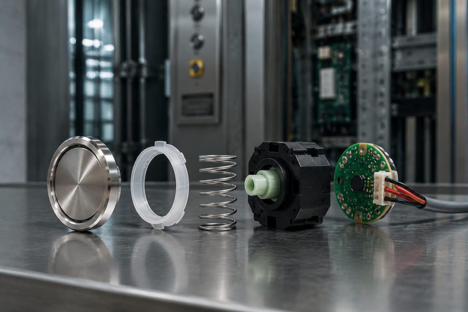
Mechanical push buttons use physical movement to actuate an internal contact or switch. They remain common because the press is clear and familiar, and many designs are serviceable as individual components.
Typical characteristics include:
- A moving face or plunger.
- Tactile and often audible feedback when pressed.
- One or more electrical contact arrangements.
- Optional lamps, LEDs, or light rings for confirmation.
- Varying bezel shapes, mounting methods, and panel cutout sizes.
Mechanical buttons can develop sticking, intermittent contacts, loose bezels, worn legends, or failed lamps. Replacement requires matching the actuator geometry and electrical arrangement, not just the face style.
Touch buttons
Touch controls use a surface sensor rather than a conventional moving plunger. Depending on the design, a user may receive feedback through a light change, sound, vibration, or display response rather than a physical click.
These controls can provide a clean panel surface, but they require the correct sensor electronics and compatible panel or controller arrangement. A standard mechanical button cannot simply replace a touch input unless the system is redesigned to accept it.
Capacitive buttons
Capacitive buttons detect changes in an electrical field when a finger approaches or touches the sensing area. They are often used in modern fixture designs and can be integrated into glass, metal, or composite control surfaces.
Capacitive controls have practical limits. Surface contamination, moisture, grounding, sensor calibration, protective covers, and environmental conditions can affect performance. They also require appropriate accessibility treatment and reliable feedback. A visually minimal interface is not automatically a suitable replacement for a tactile, mechanical button in an existing passenger elevator.
Illumination, voltage, and feedback
Illumination serves two purposes: it makes elevator buttons easier to find and it confirms a registered command. The light source may be an incandescent lamp on older equipment, an LED module, an illuminated halo, a face-lit button, or a separate indicator.
Before ordering a replacement, identify the illumination design:
- Non-illuminated: The button only provides an input.
- Lamp or LED behind the face: The legend or face lights when energized.
- Halo or ring illumination: A ring around the button changes state.
- Dual-color illumination: Different colors may distinguish standby, registered, or special conditions.
- Separate indicator: The button itself may not light; a nearby lamp or display provides feedback.
Voltage must be confirmed from the equipment documentation, wiring information, or the original component marking. Elevator buttons and their lamps can be designed for different AC or DC voltages. Connecting the wrong lamp or LED assembly can cause no illumination, reduced service life, incorrect brightness, or damage to a component.
The signal type matters as well. Some buttons present a simple dry contact closure, while others are part of a low-voltage electronic circuit or communicate through a board. A replacement must match the expected electrical behavior.
Feedback is more than lighting
A passenger should be able to tell that a button press was recognized. Mechanical travel, a click, a light change, and an audible signal are all possible feedback methods. Inaccessible or unreliable feedback can lead to repeated presses, apparent nuisance calls, and service complaints.
Do not assume a continuously lit button is defective. In some systems, illumination may be controlled by a particular operating mode, a locked-out floor state, a programmed service condition, or the fixture electronics. Diagnose the command circuit before replacing a part solely because its light behavior seems unusual.
Button boards and panel communication
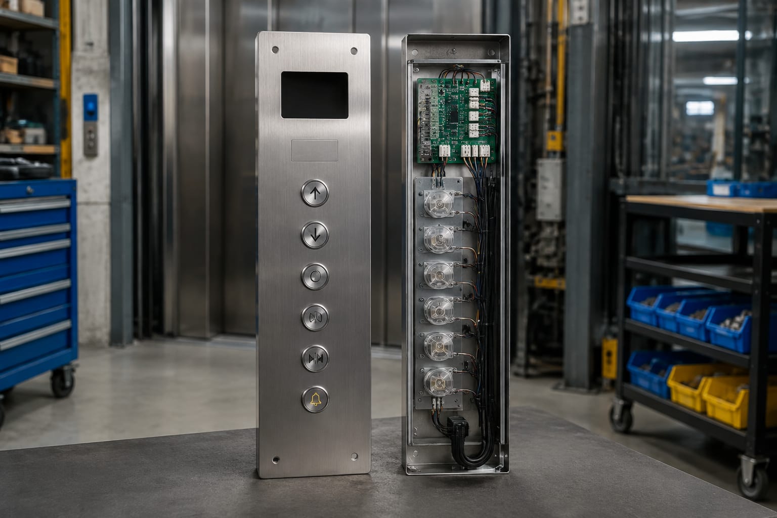
Not every elevator button is individually hardwired to a controller terminal. Many car operating panels use button boards, serial boards, or integrated fixture electronics. These assemblies reduce point-to-point wiring and allow multiple buttons, indicators, and inputs to communicate through a shared interface.
A button board may manage:
- Floor selections and call registration lights.
- Door-open, door-close, alarm, and other car functions.
- Inputs from keyswitches or restricted-access controls.
- Serial communication to the elevator controller.
- LED drive circuits and display connections.
This architecture changes diagnosis. If several buttons fail together, the issue may be a board, connector, power supply, communication line, or controller input rather than several failed button switches. If only one button fails, its contact, LED, socket, local trace, or connector position may be at fault.
For example, a Mitsubishi elevator button board should be evaluated by its exact board identification, connector arrangement, supported fixture configuration, and intended equipment family. A board that looks similar may have different pin assignments or firmware behavior.
Likewise, a Hyundai BD push button board must be matched against the installed board and panel configuration. Board-level replacement is not a generic substitute decision.
Checks before replacing a button board
- Record the part number, revision marking, and all connector labels.
- Photograph wiring and connector orientation before removal.
- Check incoming power, grounding, connectors, and communication status.
- Determine whether the symptom affects one input, multiple inputs, or the entire panel.
- Confirm whether the board requires configuration, addressing, or paired components.
- Verify the replacement’s form factor and mounting points.
Avoid swapping boards between cars simply to test a fault unless the equipment documentation supports it and the service procedure accounts for configuration differences. An incompatible board can create wider operational issues than the original failure.
Accessibility considerations
Elevator buttons must be usable by a broad range of passengers. For U.S. projects, accessibility requirements should be reviewed alongside the authority having jurisdiction, applicable elevator safety code, building code, and the fixture design. Requirements can vary based on the project scope, jurisdiction, elevator type, and whether work is a repair, alteration, or full modernization.
For practical sourcing and maintenance, evaluate these characteristics:
- Raised numerals, letters, and symbols where required.
- Braille placement and readability.
- Clear visual contrast between the control face, legend, and surrounding panel.
- A tactilely distinct emergency control arrangement where applicable.
- Adequate button size, spacing, and operable force.
- Confirming feedback through visible, audible, or tactile means as required.
- Placement that remains reachable and usable from a wheelchair.
A common mistake is specifying a visually updated button that does not preserve tactile identification. Another is replacing a button with a brighter lamp but poor legend contrast when unlit. Accessibility is determined by the complete installed interface, including mounting height, spacing, marking, and feedback, rather than a single component specification.
Common button failure symptoms
The symptom often provides the fastest route to the correct repair decision. Start with a visual inspection, then test the button, wiring, and applicable control inputs using approved procedures.
| Symptom | Possible causes | What to verify |
|---|---|---|
| Button does not register a call | Failed contact, loose wire, damaged board input, controller issue | Contact operation, wiring continuity, connector seating, associated input |
| Button registers intermittently | Worn switch, contamination, cracked solder joint, loose connector | Repeatable actuation, mechanical movement, board connection |
| Button sticks or does not return | Damaged plunger, debris, misaligned bezel, physical wear | Panel alignment, face clearance, correct mounting hardware |
| Light does not turn on | Failed lamp or LED, wrong voltage, board output problem, wiring fault | Supply voltage, illumination circuit, LED polarity where relevant |
| Light stays on | Call retained by system, shorted output, programming state, failed board component | Actual call status, controller mode, output behavior |
| Multiple buttons fail | Board power loss, communication fault, shared connector issue | Board supply, harness, communication link, common ground |
| Button is loose or rotates | Worn retaining hardware, incompatible cutout, damaged panel | Mounting dimensions, bezel, retaining nut or clips |
| Wrong floor or function responds | Miswiring, connector mismatch, incorrect board or overlay | Terminal mapping, harness identification, button legend |
A failed button should not be diagnosed by appearance alone. A cracked face is a clear replacement reason, but a healthy-looking button can have an intermittent contact. Conversely, an unlit button may still send a valid call signal.
When working on safety-related or emergency controls, follow the applicable service procedure and verify the complete function after repair. The alarm button, emergency phone activation, fire service controls, and other special functions should not be treated as routine cosmetic components.
How to specify replacement buttons
A useful replacement specification describes both the part and the installed application. “Round elevator button” is not enough information for a sourcing team or supplier to confirm compatibility.
Collect the following before requesting a replacement:
- Equipment identification: Elevator manufacturer, controller family if known, fixture manufacturer, and the exact original part number.
- Button function: Floor selection, up call, down call, door open, door close, alarm, phone, key switch, or special service control.
- Legend and marking: Number, letter, symbol, raised text, Braille, color, and language requirements.
- Physical dimensions: Face diameter or width, panel cutout, mounting depth, bezel style, retaining method, and available clearance behind the panel.
- Electrical details: Contact arrangement, normally open or normally closed behavior, voltage, AC or DC supply, current rating where applicable, and connector type.
- Illumination details: Lamp or LED, face-lit or halo-lit design, light color, voltage, and whether the light is controlled independently.
- Interface type: Individual wiring, plug-in assembly, button board connection, serial fixture system, or integrated panel module.
- Panel context: COP or hall station location, panel material, environmental exposure, and whether adjacent fixtures must match.
- Quantity and consistency: Number of units needed, spare quantity, and whether a matched set is required to prevent visible variation.
Photos are helpful, but they should include more than the front face. Capture the back of the button, labels, connectors, board markings, mounting hardware, and the panel opening. Measure the part with a scale or caliper where possible.
For a conventional illuminated replacement, review the product details for an appropriate white-and-blue Otis elevator push button only after confirming the installed equipment, mounting, voltage, and connector requirements. Product-family naming alone does not establish interchangeability across all elevator installations.
Common sourcing mistakes
- Ordering by button color without checking the part number or electrical interface.
- Reusing an old bezel or retaining clip that does not fit the new button.
- Replacing a floor button without matching its tactile and Braille marking.
- Selecting the correct face diameter but ignoring behind-panel depth.
- Assuming every LED button uses the same voltage or polarity.
- Replacing a board before checking harnesses, power, and communication.
- Mixing visually different buttons within the same panel when a consistent passenger interface is required.
For B2B importers, distributors, maintenance contractors, modernization teams, and OEM buyers, a structured specification also reduces returns and site delays. Kelevator supplies multi-brand elevator spare parts for these buyer groups; provide the installed-part details and application information needed to assess a potential match.
FAQ
Can an elevator button be replaced without replacing the entire panel?
Often, yes. Many mechanical buttons, lamps, and some plug-in modules can be replaced individually. However, integrated touch panels, proprietary fixture assemblies, damaged panel cutouts, or obsolete board systems may require a larger repair scope. Confirm the component is separately replaceable before ordering.
Why does an elevator button light up but not work?
Illumination and input signaling can be separate circuits. The button may receive power for its lamp or LED while its switch contact, wiring, board input, or controller logic has failed. Test both the visual feedback circuit and the command circuit.
Are all round elevator buttons the same size?
No. Buttons differ in face size, panel cutout, body depth, bezel geometry, mounting hardware, terminal layout, and electrical design. Measure the installed component and verify the manufacturer’s identification.
Does a hall call button select a specific elevator car?
In a typical group system, a hall call registers the passenger’s desired direction. The dispatching system determines which car responds. A destination-dispatch system works differently and may use a keypad or touchscreen rather than conventional up and down call buttons.
A replacement elevator button is most reliable when its functional role, markings, mechanical fit, electrical requirements, and panel interface are all verified together. Start with the original part identification and clear photos of the complete assembly, then compare the candidate part against those details before purchase or installation.