
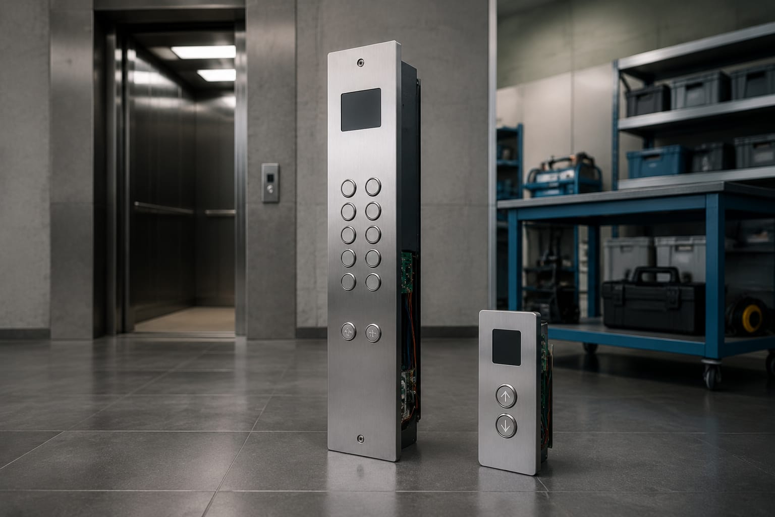
An elevator button panel is the interface between passengers, the elevator control system, and, in some cases, building emergency operations. Selecting or replacing one is not simply a matter of matching the number of buttons. The panel must suit its location, controller architecture, wiring, mounting cutout, accessibility requirements, and the building’s intended operation.
The two main panel types are the car operating panel (COP) inside the cab and the landing operating panel (LOP) outside the elevator. Both may contain buttons, indicators, and electronics, but they serve different functions and should be specified, ordered, and tested differently.
COP and LOP explained
A car operating panel (COP) is installed inside the elevator car. It allows passengers to select floors and typically includes door controls, an alarm button, emergency communication equipment, and position information. Depending on the elevator and local requirements, it may also include firefighter operation controls, key switches, or other restricted functions.
A landing operating panel (LOP) is mounted at an elevator entrance on a floor. Its core purpose is to register an up or down hall call. A single-button LOP is common at terminal floors, while a two-button LOP is typically used at intermediate floors where passengers may travel in either direction.
| Attribute | COP | LOP |
|---|---|---|
| Location | Inside the elevator car | At the landing entrance |
| Primary user action | Select a destination and car functions | Request travel direction |
| Typical controls | Floor buttons, door open/close, alarm, emergency communication | Up/down call buttons |
| Typical displays | Car position, direction, messages, capacity or service status | Direction arrows, arrival indicator, floor or destination information |
| Interface considerations | Cab finish, internal wiring, emergency functions, accessibility | Wall or jamb mounting, call logic, indicators, weather/exposure where applicable |
In a conventional collective-selective system, a passenger presses an up or down LOP call button, then selects a floor after entering the car at the COP. A destination dispatch system changes that workflow: the passenger enters the destination at a landing device, and the system directs the passenger to a car. That arrangement may reduce or change the role of traditional COP floor buttons.
When planning a replacement, identify whether the part is a COP, LOP, or a related assembly such as an indicator panel, destination terminal, transom display, or hall lantern. Similar-looking panels can have entirely different electrical interfaces and mounting requirements.
Parts inside an elevator button panel
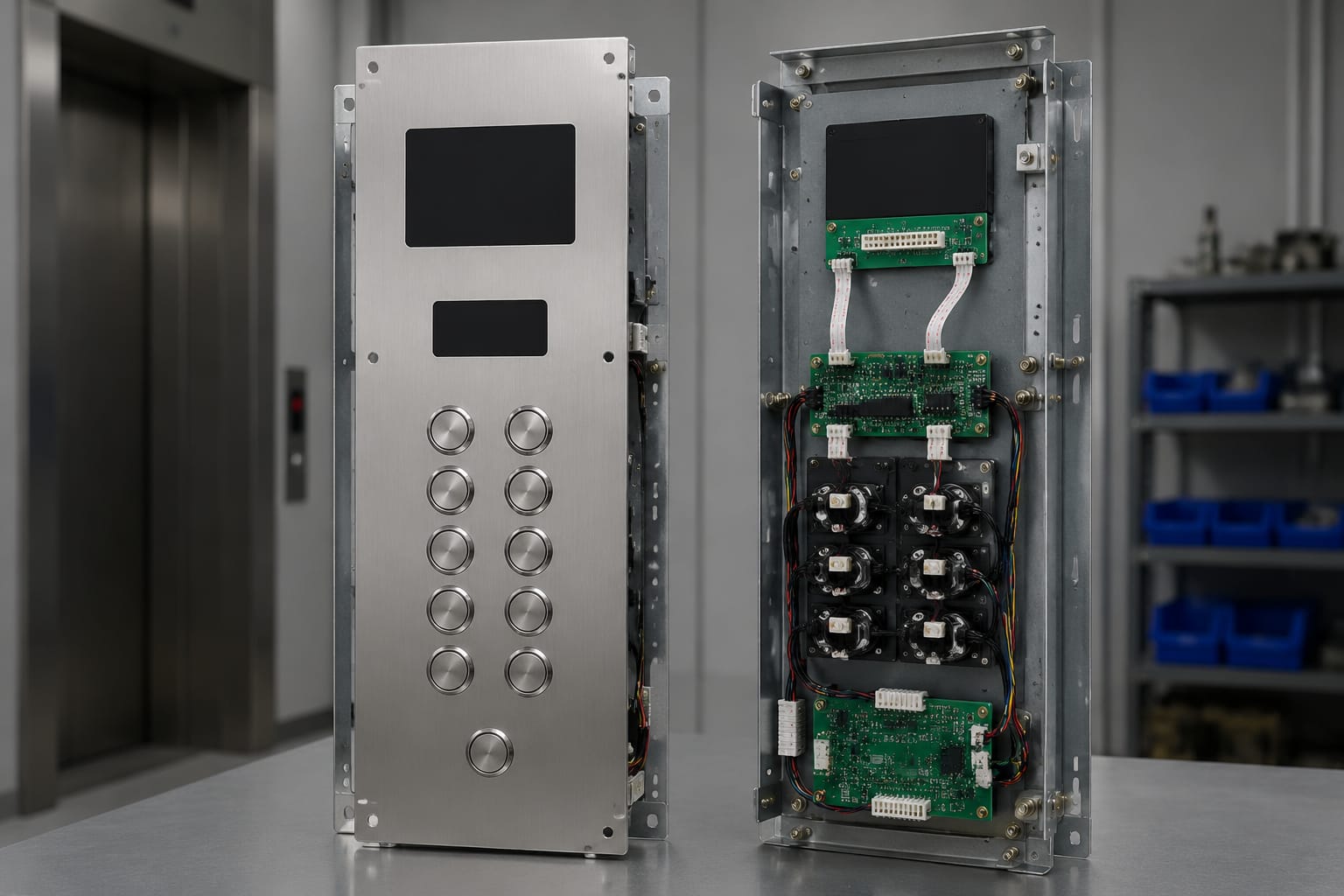
An elevator button panel is usually an assembly rather than one interchangeable component. Its visible faceplate is only one part of the system.
Common COP and LOP components include:
- Faceplate or fascia: The finished front surface with cutouts, engraving, braille or tactile markings, and mounting points.
- Pushbutton assemblies: Mechanical or capacitive controls that register calls. They may include illuminated halos, legends, arrows, or color-coded status lights.
- Button contacts and illumination elements: The switch and indicator portions of a button. Their voltage, current, color, and electrical configuration must be compatible with the controller.
- Position indicator: A display that communicates the current floor, travel direction, or service condition. It may be an LED segment display, dot-matrix display, LCD, or another specified format.
- Hall lantern or direction indicator: A landing-side visual signal that shows approaching car direction, and in some installations, additional arrival information.
- Panel control board: A PCB that reads button inputs, drives lights or displays, and communicates with the elevator controller.
- Harnesses, cables, and connectors: The interface between panel components and the traveling cable, controller, or related fixtures.
- Mounting hardware and back box: Brackets, studs, screws, and enclosures that secure the assembly while providing clearance for wiring and electronics.
- Emergency and service devices: Depending on application, these can include alarm controls, emergency communication hardware, key switches, inspection-related controls, or firefighter operation equipment.
A failed button is sometimes replaceable by itself, but a visible failure does not always originate at the button. A dark indicator can result from an illumination issue, damaged harness, connector fault, board problem, controller output issue, or configuration mismatch. Diagnose the circuit and command path before replacing a larger assembly.
Button and display configurations
Panel configuration should reflect building traffic, use conditions, controller capability, and accessibility needs. Floor count alone is not enough.
Conventional buttons and hall calls
Traditional COPs use one button per served landing, supplemented by door open, door close, alarm, and other applicable controls. Conventional LOPs generally use:
- One directional call button at a terminal landing
- Up and down call buttons at an intermediate landing
- A single call button where a system’s operating design calls for it
- Arrival indicators or hall lanterns when specified
Confirm the button legend style, illumination behavior, and whether the input is momentary, maintained, normally open, normally closed, or managed through a serial fixture network. These characteristics are controller-dependent.
Displays and indicators
A position display may be standalone or integrated into the COP. Landing displays can be included in an LOP, mounted separately above the entrance, or incorporated into a hall fixture package.
When selecting a display, verify:
- Display technology and appearance: LED segments, dot-matrix, LCD, or other format.
- Character size, viewing angle, and brightness appropriate to the site.
- Floor designation format, including letters, numbers, basement labels, and special floors.
- Direction arrows, chime interface, and any message or service-status capability.
- Power, data protocol, connector type, and controller compatibility.
For projects using integrated call and display fixtures, review the complete electrical interface rather than treating the screen and buttons as independent components. An LCD outbound call panel and step system component is an example of the type of assembly that requires matching its operating method and connection details to the receiving system.
Destination dispatch terminals
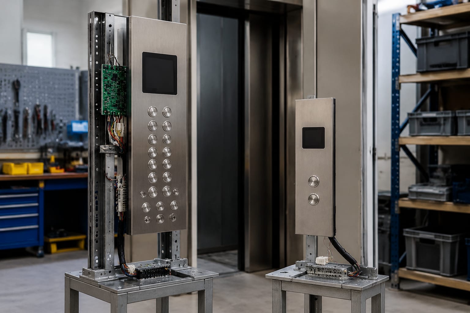
Destination dispatch terminals accept a passenger’s floor request at the landing and assign a car. These are not standard up/down LOPs. Before replacing one, confirm the controller’s dispatch system, software configuration, communications protocol, screen behavior, credentialing features if present, and physical mounting arrangement. A panel that is electrically functional but not recognized by the dispatch system may not be usable.
Faceplate materials and dimensions
Faceplates need to fit the opening, meet the desired appearance, and withstand the environment. Stainless steel is widely used because it is durable, cleanable, and appropriate for many commercial interiors. Other finishes may include coated metals, bronze-toned finishes, patterned stainless, or manufacturer-specific architectural finishes.
Material selection should account for:
- Fingerprint visibility and cleaning expectations
- Scratch and impact resistance
- Corrosion exposure, particularly near exterior entrances or humid environments
- Matching existing cab, door, jamb, or wall finishes
- Engraving contrast and the legibility of legends
- Fire rating, vandal-resistance, or project-specific requirements where applicable
Do not order by the nominal panel size alone. Measure and document:
- Overall faceplate height and width
- Plate thickness
- Cutout dimensions and corner radii
- Button hole diameter and center-to-center spacing
- Display opening dimensions
- Stud locations, mounting-hole locations, and thread type
- Available recess or wall-box depth
- Cable exit direction and required clearance behind the panel
A replacement faceplate can look correct from the front and still fail installation because its studs do not align, its back box is too shallow, or its display cutout differs by a small amount. Clear front and rear photographs, a measured drawing, and a sample where available reduce these risks.
Board, cable, and connector matching
Compatibility is the central risk in elevator button panel replacement. A matching faceplate, button style, or connector pin count does not prove that the panel will work with the existing controller.
The board and cable must be evaluated as a matched interface. Confirm the following before purchase or installation:
| Check | Why it matters |
|---|---|
| Elevator controller make, model, and revision | Defines supported fixture inputs, outputs, and communications |
| Panel or board part number | Identifies the intended assembly and revision |
| Cable part number and length | Avoids improper routing, insufficient reach, or incorrect wiring |
| Connector family, gender, keying, and pin count | Physically similar connectors may have different pin assignments |
| Pinout and wire mapping | Prevents power, signal, and common connections from being crossed |
| Supply voltage and load | Protects buttons, boards, displays, and controller outputs |
| Communication method | Determines whether the fixture uses discrete wiring, serial data, CAN, RS-485, or a proprietary network |
| Firmware or configuration dependency | Some panels need controller settings or compatible software versions |
| Mounting and grounding arrangement | Supports reliable operation and helps avoid noise or mechanical fit issues |
For example, a 10-pin cable cannot be accepted solely because both ends have 10 positions. Keying, conductor assignment, shielding, wire gauge, connector series, and panel board assignment still need confirmation. When replacing a known cable assembly, compare the old label, connector photos, cable length, wire count, and pinout. A 10-pin COP/LOP connection cable should be selected against the specific panel and system documentation, not by appearance alone.
Avoid splicing or adapting fixture wiring unless the responsible elevator professional has confirmed the circuit design, code implications, enclosure requirements, strain relief, and test procedure. Improvised connections can create intermittent faults that are difficult to trace after the panel is closed.
Accessibility and emergency controls
COP and LOP design has a direct effect on accessible use. In the United States, applicable requirements may involve the Americans with Disabilities Act, building codes, elevator safety codes, project specifications, and the authority having jurisdiction. The exact obligations depend on the building, scope of work, jurisdiction, and whether the project is new construction, alteration, or maintenance.
For accessible panel design, evaluate:
- Button height, reach range, and location
- Tactile legends and braille placement
- Raised character quality and legibility
- Visual contrast between controls, legends, and the panel background
- Audible and visual feedback for registered calls and arrival information
- Floor designation clarity
- Door open and alarm control identification
- Emergency communication accessibility and operation
- Clearance around controls and absence of sharp edges
Emergency and restricted functions require special care. Alarm buttons, emergency communications, key switches, firefighter operation controls, and service indicators should be placed and marked according to the applicable design and code requirements. Do not substitute a generic button panel for an existing panel that carries emergency-related functions without verifying the complete operating and compliance impact.
Accessibility also depends on installation quality. A compliant fixture specified at the correct height can become noncompliant if a faceplate is shifted, a button binds, tactile labeling is incomplete, or visual indicators are not working.
Customization and modernization options
Modernization provides an opportunity to improve usability, appearance, maintainability, and system consistency. It also creates compatibility risk when legacy controller architecture is retained.
Common customization options include:
- Custom floor labels, engraving, and tactile markings
- Stainless steel grades and decorative finish selections
- Button shape, bezel style, illumination color, and halo lighting
- Integrated or separate position indicators
- Hall lanterns, chimes, and directional arrows
- Vandal-resistant fixtures for high-abuse environments
- Key switch and credential-reader provisions
- Destination dispatch interfaces
- Flush, surface, jamb, or transom mounting
- Matching COP, LOP, and indicator finishes across an elevator bank
For a partial modernization, determine which existing components will remain in service. Reusing a controller while changing fixtures may require interface boards, harness changes, configuration work, or compatible button modules. Replacing only the faceplate may preserve the electronics but limit the possible layout. Replacing a complete COP can simplify appearance coordination but may expand wiring and commissioning work.
When sourcing components across brands or for legacy systems, organize the package by function: faceplate, buttons, display, board, harness, connectors, mounting hardware, and documentation. Kelevator supplies multi-brand elevator spare parts for B2B buyers, including elevator control panel button boards and related accessories. For any replacement assembly, request or retain the exact identifiers and technical information needed to verify fit with the installed system.
Panel testing and commissioning
A panel should be tested after installation, before it is treated as ready for normal service. Testing is not limited to seeing whether an illuminated button turns on.
A practical commissioning sequence includes:
- Inspect installation quality. Confirm the panel is secure, flush as intended, free of sharp edges, and does not pinch cables or bind buttons.
- Verify wiring and connections. Check connector keying, seating, strain relief, grounding where specified, and cable routing before applying power.
- Test every input. Operate each floor button, hall call, door control, alarm control, key switch, and other installed function.
- Confirm visual feedback. Verify button illumination, floor displays, directional arrows, service messages, and indicators in the expected states.
- Confirm audible feedback. Test chimes, audible acknowledgments, and emergency communication equipment as applicable.
- Run functional calls. Make calls from each landing and car position to confirm direction logic, button cancellation, and display behavior.
- Check accessibility features. Inspect tactile markings, braille, contrast, button travel, and required audible/visual signals.
- Test fault conditions where permitted. Confirm that a disconnected or failed device produces the expected controller response and does not create an unsafe condition.
- Record final configuration. Keep panel, board, cable, and controller identifiers along with wiring changes and test results.
Commissioning should be performed by qualified personnel using the procedures and safety practices appropriate to the equipment and project. A panel can appear operational while still having incorrect floor mapping, reversed arrows, missed calls, intermittent communications, or incomplete emergency functions.
Common replacement mistakes to avoid
The most frequent replacement problems are preventable during identification and ordering:
- Ordering a panel from a photo without verifying measurements and rear-side details
- Treating a matching connector shape as proof of electrical compatibility
- Replacing a button when the board, harness, or controller output is actually at fault
- Assuming a display will work without checking communications and configuration
- Omitting braille, tactile legends, or required emergency controls during a cosmetic update
- Ignoring cable bend radius and clearance behind a shallow panel
- Mixing different finish batches across adjacent fixtures
- Failing to document the original part number and wire mapping before removal
- Closing the panel before all functions, indicators, and call logic have been tested
FAQ
Can a COP be used as an LOP?
Usually not without a purpose-designed configuration. A COP and LOP differ in function, layout, wiring, and controller logic. Even when they share a button style or faceplate finish, their assemblies are not automatically interchangeable.
Are elevator buttons universal?
No. Button diameter, mounting method, illumination voltage, contact arrangement, legend style, electrical load, and communications interface can all vary. Confirm the installed panel and controller requirements before selecting a replacement.
Should a whole panel be replaced when one button fails?
Not necessarily. First determine whether the fault is isolated to the button assembly. If the faceplate, board, harness, and other buttons are in good condition, replacing the failed component may be appropriate. A broader replacement may make sense when parts are obsolete, finishes no longer match, multiple failures are occurring, or a modernization is already planned.
What information is needed to source an elevator button panel?
Provide the elevator controller make and model, panel and board part numbers, clear front and rear photos, overall dimensions, button layout, connector details, cable information, mounting details, and the function of each control. For a display or intelligent fixture, include system configuration and communication details where available.
Start a replacement plan by documenting the installed COP or LOP before removal, then compare the proposed panel’s mechanical, electrical, functional, and accessibility requirements against that record. This approach helps maintenance teams and sourcing groups avoid a part that fits the opening but does not operate correctly.
Related product references
For practical catalog examples related to this topic, review Elevator Control Panel Button Board lift accessories, 3300 3600 5500 LOP COP Control Panel Connection Cable 10 Pin Core lift accessories, and Outbound call LCD panel STEP system elevator parts. Confirm the exact model, dimensions, ratings, and connectors before ordering.