
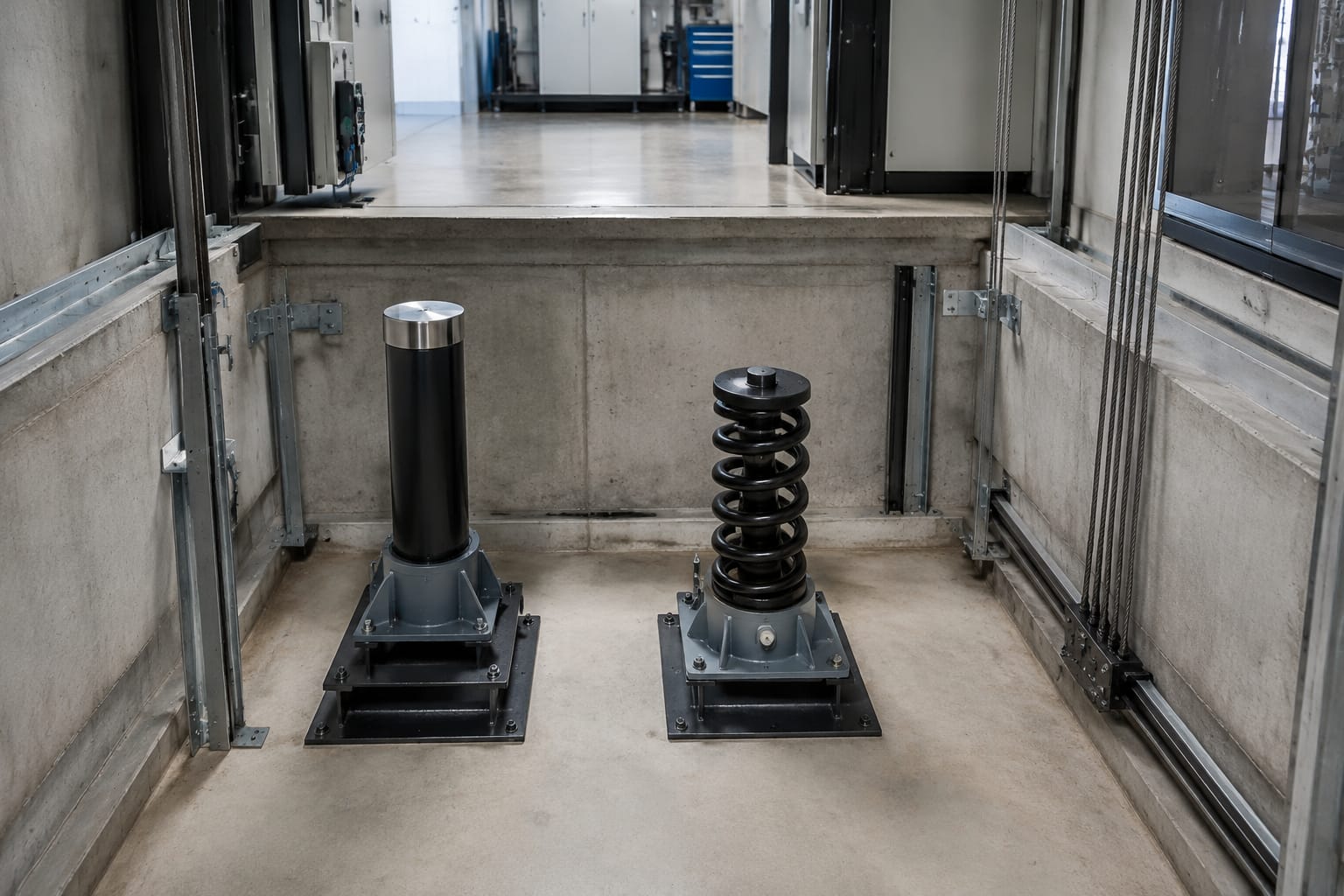
An elevator buffer is a last-resort safety device installed in the hoistway pit. It absorbs or dissipates energy if an elevator car or counterweight travels beyond its normal bottom stopping position. The correct buffer lift selection depends on the moving mass, rated speed, available stroke, pit geometry, and the safety code and manufacturer requirements that govern the installation.
For maintenance and sourcing teams, the practical rule is simple: do not treat a buffer as a generic pit component. Its type, stroke, rated capacity, speed range, mounting arrangement, and electrical proving provisions must match the application. Inspect buffers as part of routine pit work, and replace any unit with leakage, structural damage, excessive corrosion, missing identification, or an uncertain operating history.
What an elevator buffer does
Buffers sit beneath the car and counterweight travel paths in the pit. Under normal operation, neither the car nor counterweight should contact them. Their role begins only when other stopping and protective systems have not prevented overtravel at the bottom of the hoistway.
A buffer must manage the kinetic energy of the descending component without creating an unsafe deceleration or allowing the component to bottom out on pit structure. Depending on its design, it does this by:
- Compressing a spring and storing energy temporarily
- Forcing oil through controlled passages to convert motion into hydraulic resistance
- Providing a defined stopping stroke for the car or counterweight
- Operating a switch or associated electrical proving arrangement where the design requires it
The buffer is one layer in a larger safety system. It does not replace correct terminal stopping, leveling, governor, safeties, braking, or maintenance practices. A buffer that has been struck should be treated as a significant event: establish why overtravel occurred before simply returning the elevator to service.
Oil buffers versus spring buffers
Spring and oil buffers have different operating characteristics. The right choice is determined by the elevator’s design and the governing requirements, not simply by what is already stocked in the warehouse.
| Attribute | Spring buffer | Oil buffer |
|---|---|---|
| Energy management | Compresses a spring and returns stored energy | Uses hydraulic resistance to dissipate energy through a controlled stroke |
| Typical suitability | Lower-speed applications, subject to applicable requirements | Higher-speed or higher-energy applications, subject to applicable requirements |
| Reset behavior | Re-expands after compression | Usually requires confirmation that the plunger has returned fully and oil level is correct |
| Main inspection focus | Broken coils, deformation, seating, corrosion, free height | Oil leakage, plunger condition, return position, corrosion, and mounting |
| Common sourcing risk | Matching only outer dimensions while ignoring load and travel | Ordering by cylinder size while missing stroke, speed, switch, or mounting details |
Spring buffers
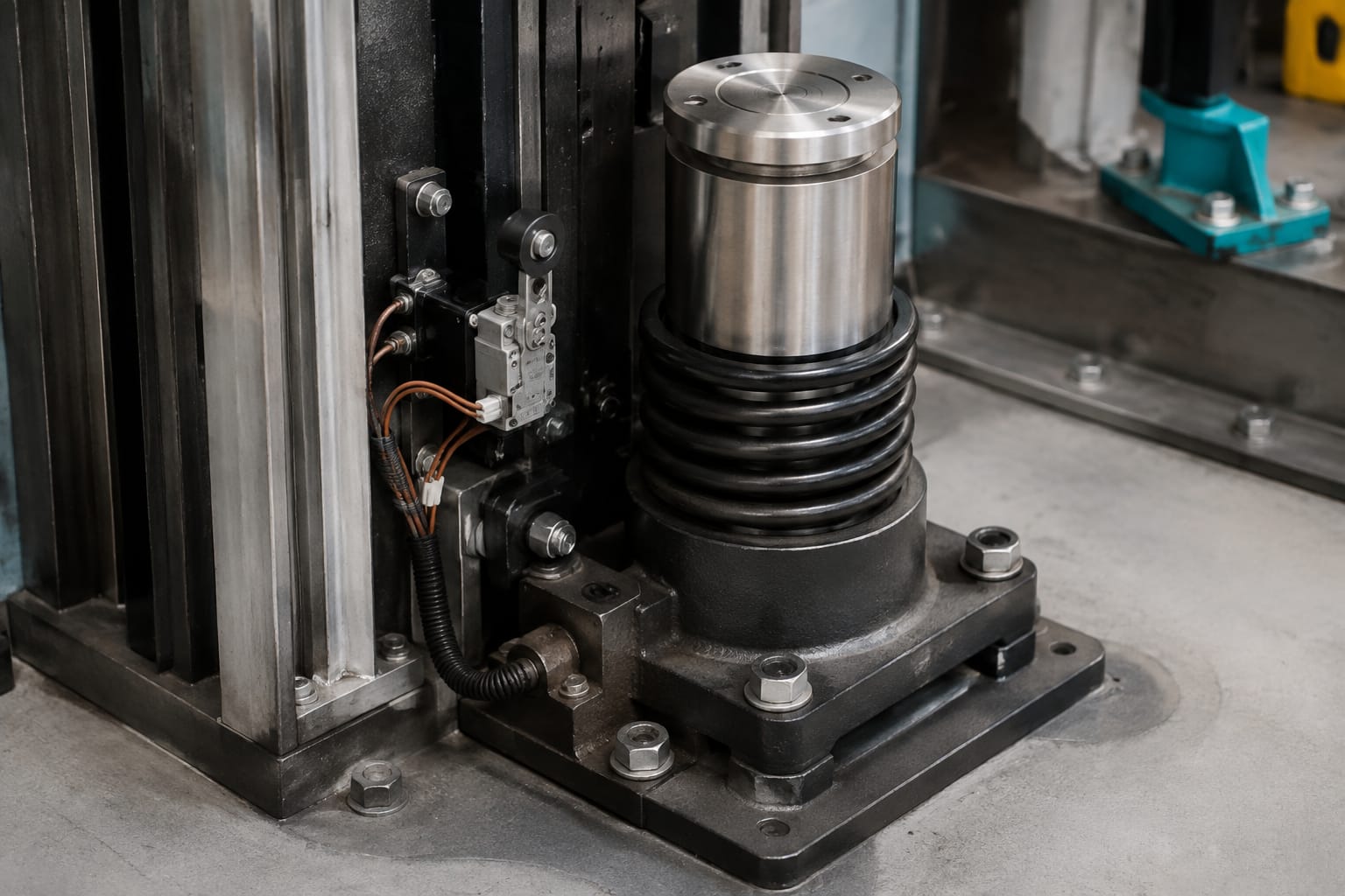
A spring buffer is mechanically straightforward: a car or counterweight compresses one or more springs during contact. Its stopping behavior is influenced by spring rate, available compression travel, and the load applied.
These buffers are often valued for their simple construction. However, they should not be assumed to fit every low-rise installation. Verify the specified rated load, maximum permitted speed, compressed height, free height, and required clearance. A spring that looks intact can still be unsuitable if it has taken a permanent set, lost its required free height, or has corrosion that affects its integrity.
The rebound inherent to a spring design is also a reason that system suitability matters. The entire installation must be designed around the required behavior after contact, rather than around the buffer alone.
Oil buffers
Oil buffers, also called hydraulic buffers, use a plunger moving into an oil-filled cylinder. Internal flow restriction creates controlled resistance over the available stroke. This makes them suitable for applications where more gradual and controlled deceleration is required.
An oil buffer requires more condition checks than a spring unit. Inspectors should look for external oil, a wet cylinder, damaged seals, a scored or rusted plunger, loose caps, and evidence that the plunger is not fully returned. Oil loss can reduce performance, while a plunger that does not reset can create a clearance or operating issue.
For procurement, an elevator hydraulic oil buffer should be identified by its complete nameplate and physical configuration, not merely as an “oil buffer.” Capacity, stroke, extended and retracted height, mounting, and electrical components may all differ across apparently similar units.
Car and counterweight applications
Most traction elevator installations have buffers under both the car and the counterweight. They may be physically similar, but they should not be presumed interchangeable.
The force at each location depends on the mass that can reach the buffer. For the car side, this may involve the car weight plus its applicable load condition. For the counterweight side, the relevant mass and balance relationship differ. The elevator manufacturer’s documentation and applicable code requirements establish the required calculations and buffer arrangement.
Before replacing any buffer, determine:
- Whether the buffer is installed below the car, counterweight, or both
- The number of buffers supporting that travel path
- The rated car capacity and car weight
- The counterweight configuration and any modernization changes
- The rated elevator speed and suspension arrangement
- The original equipment manufacturer’s required buffer designation
- Whether the pit has been altered, including changes to sill support, compensation equipment, or clearances
Modernization work deserves extra caution. A controller, machine, suspension, car enclosure, or counterweight modification can affect travel, mass, or operating speed. Retaining an existing buffer without confirming its rating against the final modernization configuration can leave an otherwise upgraded elevator with an incompatible pit safety component.
Stroke, speed, and load considerations
Stroke is the vertical distance over which a buffer can absorb energy. It is not an optional dimension. A replacement with inadequate stroke may stop the car or counterweight too abruptly or fail to provide the travel expected by the installation. A unit with the right stroke but the wrong capacity can be equally unsuitable.
Use the buffer’s identification plate, elevator data plate, controller documentation, job specifications, and original manufacturer records to establish the required values. At a minimum, compare the following before approving a replacement:
| Check | Why it matters |
|---|---|
| Rated elevator speed | Buffer suitability is closely tied to the energy at impact and required stopping performance. |
| Supported mass or rated capacity | The buffer must be rated for the actual car or counterweight application. |
| Usable stroke | Confirms the buffer can travel its intended distance without bottoming prematurely. |
| Overall height | Affects pit clearances and engagement position. |
| Retracted and extended dimensions | Confirms proper car/counterweight clearance and post-contact position. |
| Base footprint and bolt pattern | Prevents field modifications that weaken mounting or misalign the buffer. |
| Plunger or spring centerline | Must align with the striking plate or contact surface. |
| Switch configuration | Ensures compatibility with the existing safety circuit or controller input. |
| Environmental condition | Moisture, cleaning chemicals, and pit water can affect corrosion protection and seals. |
Do not substitute a shorter unit solely because it fits below the striking plate, and do not add shims, fabricated pedestals, or modified mounting hardware without engineered approval. These changes can alter alignment, engagement height, structural load transfer, and required refuge-space geometry.
For oil buffers, verify the specified operating position. Some designs require a particular plunger extension at rest, and a buffer that remains depressed after an event may not meet its intended condition until it has reset and been inspected.
Buffer switches and electrical proving
A buffer switch is commonly used to indicate that a buffer has been compressed or is not in its normal position. Depending on the elevator design, this can prevent operation, initiate a fault condition, or provide a monitored status input. The wiring logic and required function vary by controller, code edition, and equipment design.
The important point is that a switch is a safety-related component, not a convenience accessory. A switch that is bypassed, misadjusted, damaged, or wired with an incorrect contact arrangement can create both troubleshooting problems and an unsafe condition.
When inspecting or replacing a switch, confirm:
- The manufacturer and exact buffer or switch model
- Normally open or normally closed contact arrangement
- Number of contacts and terminals
- Actuator style, lever orientation, and travel
- Electrical rating required by the existing circuit
- Cable entry, connector, conduit, and enclosure arrangement
- Mounting hole pattern and adjustment range
- The controller’s expected normal and operated state
For replacement sourcing, use the identifying information from the existing assembly and the wiring documentation. Kelevator lists 3300/3600 elevator buffer switches for applications where that specific series is required, while Mitsubishi elevator buffer switches should be matched to the applicable equipment and part details rather than selected by appearance.
Never permanently jumper a buffer switch to keep an elevator running. If a temporary troubleshooting procedure is permitted by the responsible authority and company safety process, it must be controlled, documented, and removed before the elevator returns to normal service.
Leakage, corrosion, and damage checks
Pit inspections often reveal buffer problems before a full failure occurs. The inspection should include the buffer body, moving parts, base, fasteners, surrounding pit condition, and contact surface above the buffer.
Oil buffer inspection checklist
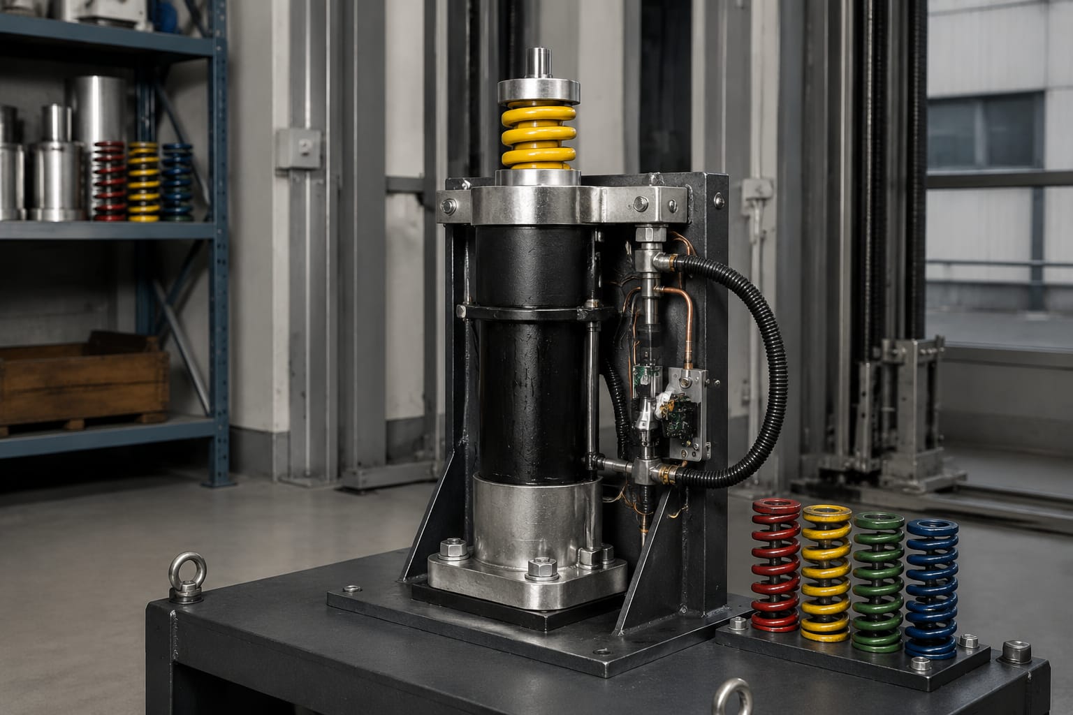
Check oil buffers for:
- Oil film, drips, puddling, or residue around the cylinder and base
- A damaged, bent, scored, pitted, or corroded plunger
- A plunger that is not fully returned when the buffer should be at rest
- Loose fasteners, cracked welds, damaged brackets, or movement at the base
- Missing, illegible, or inconsistent identification plates
- Signs of unauthorized filling, incorrect fluid, or unapproved repairs
- Misalignment between the plunger and the car or counterweight striking plate
- Water accumulation or contaminants in the pit that could affect the unit
External oil does not automatically prove a buffer is unusable, but it warrants prompt assessment. Clean the area only after recording the condition, then determine the source. Oil may migrate from other equipment, but assuming this without verification can conceal a failing seal.
Spring buffer inspection checklist
Check spring buffers for:
- Cracked, broken, bowed, or visibly uneven coils
- Corrosion, especially at lower coils and seating surfaces
- Loss of free height or permanent compression
- A spring that is not centered in its housing or is rubbing adjacent structure
- Loose bases, anchors, guide rods, caps, or retaining hardware
- Damage to the striking plate or contact surface
- Inadequate clearance, altered supports, or misalignment
Corrosion in a damp pit is more than cosmetic. Surface rust may be manageable under an approved maintenance process, but deep pitting, flaking material, compromised fasteners, and reduced section thickness require replacement evaluation. Address the moisture source as well; otherwise, a new buffer can deteriorate quickly.
Conditions that require escalation
Remove the elevator from normal operation or follow the responsible party’s safety procedure when inspection identifies an unsafe condition, a buffer impact event, uncertain ratings, failed electrical proving, structural damage, or a condition that cannot be assessed in the field. The exact response depends on local requirements, company procedures, and the authority having jurisdiction.
Replacement identification and installation
A correct replacement begins with documentation. The best identification package includes clear photographs of every side of the buffer, the nameplate, dimensions, the mounting base, the switch assembly, and the car or counterweight contact point.
Record these details before ordering:
- Buffer manufacturer, model, serial number, and all nameplate ratings.
- Buffer type: oil/hydraulic or spring.
- Location: car side, counterweight side, or both.
- Overall height at rest and the available pit clearance.
- Stroke or spring compression travel.
- Base dimensions, anchor locations, and bolt size.
- Plunger diameter or spring diameter, where applicable.
- Switch make, model, contact configuration, and wire termination details.
- Elevator rated speed, capacity, and modernization status.
- Any observed damage, oil condition, alignment concern, or evidence of prior impact.
Avoid common replacement mistakes:
- Matching the old part by visual similarity alone
- Reusing damaged anchors or mounting hardware
- Installing a buffer with a different contact elevation without approval
- Assuming a car-side buffer is correct for the counterweight side
- Replacing a switch without proving its circuit behavior at the controller
- Filling or servicing an oil buffer with unspecified fluid
- Omitting a review of the cause after a buffer has been contacted
Installation should follow the buffer manufacturer’s instructions, the elevator manufacturer’s requirements, applicable safety code, and the site’s authorized work procedures. Secure the car and counterweight as required, control the hoistway, and do not rely on normal stopping devices while working in the buffer area.
After mounting, confirm that the buffer is plumb and aligned with the striking plate, all specified hardware is installed and tightened to the documented requirement, electrical wiring is protected, and no interference exists through the expected travel range.
Post-service inspection and testing
Installation is not complete when the buffer is bolted down. The elevator must be inspected and tested under the procedures required for the equipment and jurisdiction before normal service resumes.
A post-service review should include:
- Verification of the replacement part number and ratings against the approved requirement
- Confirmation of mounting, alignment, fasteners, and pit clearances
- Inspection for oil leakage after servicing an oil buffer
- Verification that the plunger or spring is in its correct normal position
- Functional check of buffer switches and the related controller response
- Confirmation that terminal stopping and normal operation are correct
- Review of any fault records or event information related to the original condition
- Documentation of the condition found, work performed, part identification, and test results
Testing a buffer system is specialized work. Do not create an impact condition merely to “see whether it works” unless that procedure is specifically required, planned, authorized, and performed by qualified personnel using the applicable method. In most routine replacement work, inspection, electrical verification, dimensional confirmation, and the prescribed acceptance or maintenance tests provide the appropriate path.
For multi-brand spare-parts sourcing, provide the complete identification record to Kelevator or another qualified supplier. A complete record gives the supplier and maintenance team the information needed to evaluate compatibility while keeping final selection tied to the elevator’s actual ratings and installation conditions.
Related product references
For practical catalog examples related to this topic, review Hydraulic oil pressure buffer lift parts elevator accessories, 3300 3600 Elevator Buffer Switch Parts lift parts, and Elevator buffer switch – – Mitsubishi lift parts. Confirm the exact model, dimensions, ratings, and connectors before ordering.